ENGINE (YP250R)
3-21
EAS20470
ENGINE (YP250R)
EAS20520
ADJUSTING THE VALVE CLEARANCE
The following procedure applies to all of the
valves.
IP
• Valve clearance adjustment should be made
on a cold engine, at room temperature.
• When the valve clearance is to be measured or
adjusted, the piston must be at top dead center
(TDC) on the compression stroke.
1. Remove:
• Storage box
Refer to “GENERAL CHASSIS” on page 4-1.
2. Remove:
• V-belt case air filter cover “1”
3. Remove:
• Spark plug cap “1”
• Spark plug
• Tappet covers “2”
• Camshaft sprocket cover “3”
4. Remove:
• Timing mark accessing plug “1”
5. Measure:
• Valve clearance
Out of specification → Adjust.
▼▼▼▼▼▼▼▼▼ ▼ ▼▼▼▼ ▼ ▼▼▼▼ ▼ ▼▼▼▼ ▼ ▼▼▼▼ ▼▼▼
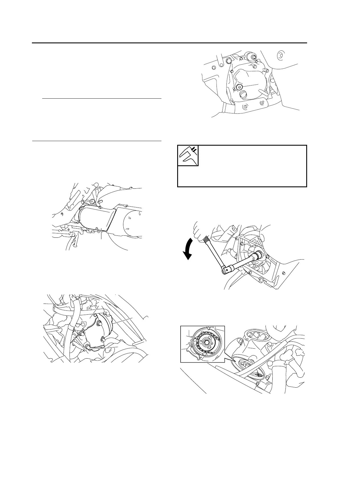
a. Turn the primary sheave nut on the left side
of the crankshaft counterclockwise to turn the
crankshaft.
b. When the piston is at TDC on the compres-
sion stroke, align the “I” mark “a” on the cam-
shaft sprocket with the stationary pointer “b”
on the cylinder head.
c. Align the “I” mark “c” on the generator rotor
with the stationary pointer “d” on the genera-
tor cover.
1
1
2
2
3
Valve clearance (cold)
Intake
0.08–0.12 mm (0.0031–0.0047 in)
Exhaust
0.16–0.20 mm (0.0063–0.0079 in)
1
a
b
 Loading...