VALVES AND VALVE SPRINGS (YP125R)
5-23
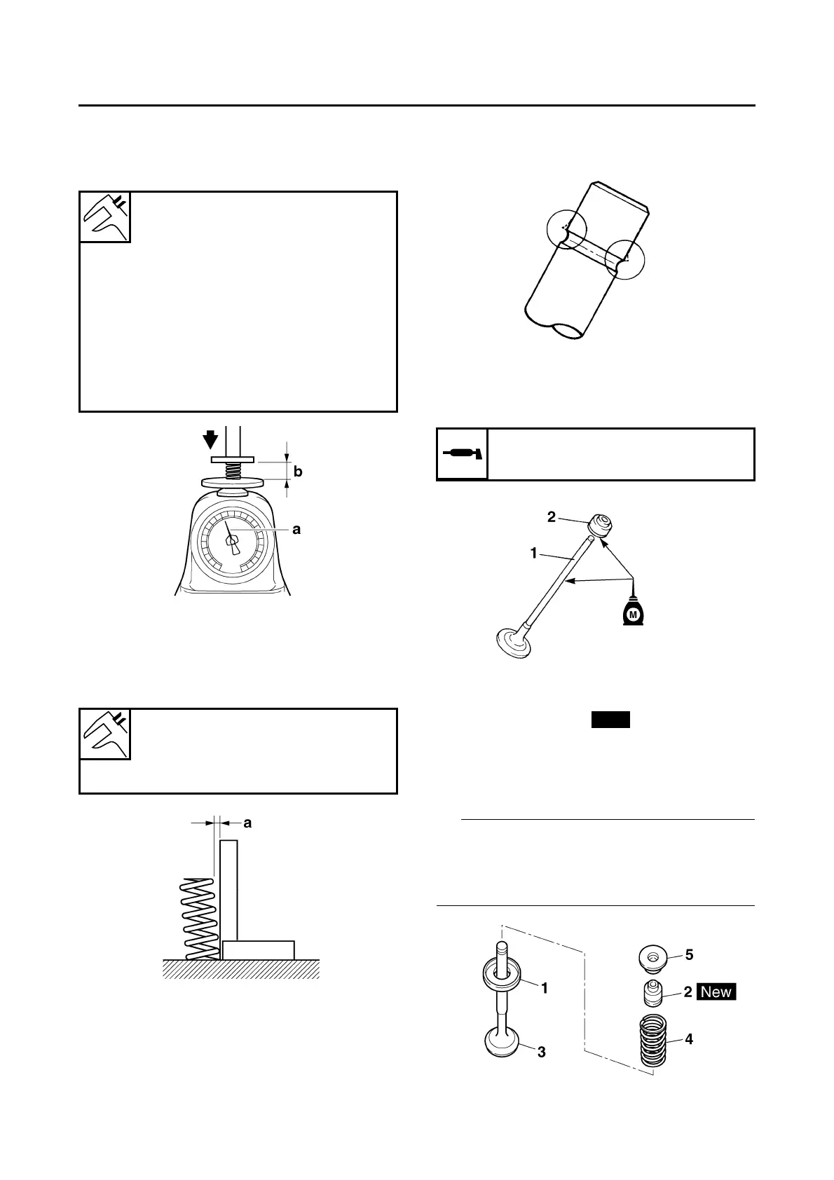
2. Measure:
• Compressed valve spring force “a”
Out of specification → Replace the valve
spring.
3. Measure:
• Valve spring tilt “a”
Out of specification → Replace the valve
spring.
EAS37P1018
INSTALLING THE VALVES
The following procedure applies to all of the
valves and related components.
1. Deburr:
• Valve stem end
(with an oil stone)
2. Lubricate:
• Valve stem “1”
• Valve stem seal “2”
(with the recommended lubricant)
3. Install:
• Lower spring seat “1”
• Valve stem seal “2”
• Valve “3”
• Valve spring “4”
• Upper spring seat “5”
(into the cylinder head)
IP
• Make sure each valve is installed in its original
place.
• Install the valve springs with the larger pitch “a”
facing up.
Installed compression spring
force (intake)
140–162 N (14.28–16.52 kgf,
31.47–36.42 lbf)
Installed compression spring
force (exhaust)
140–162 N (14.28–16.52 kgf,
31.47–36.42 lbf)
Installed length (intake)
35.30 mm (1.39 in)
Installed length (exhaust)
35.30 mm (1.39 in)
b. Installed length
Spring tilt (intake)
2.5°/1.8 mm
Spring tilt (exhaust)
2.5°/1.8 mm
Recommended lubricant
Molybdenum disulfide oil
New
 Loading...