CRANKSHAFT (YP125R)
5-59
EAS37P1064
ASSEMBLING THE CRANKCASE
1. Thoroughly clean all the gasket mating sur-
faces and crankcase mating surfaces.
2. Apply:
• Sealant
(onto the crankcase mating surfaces)
IP
Do not allow any sealant to come into contact
with the oil gallery.
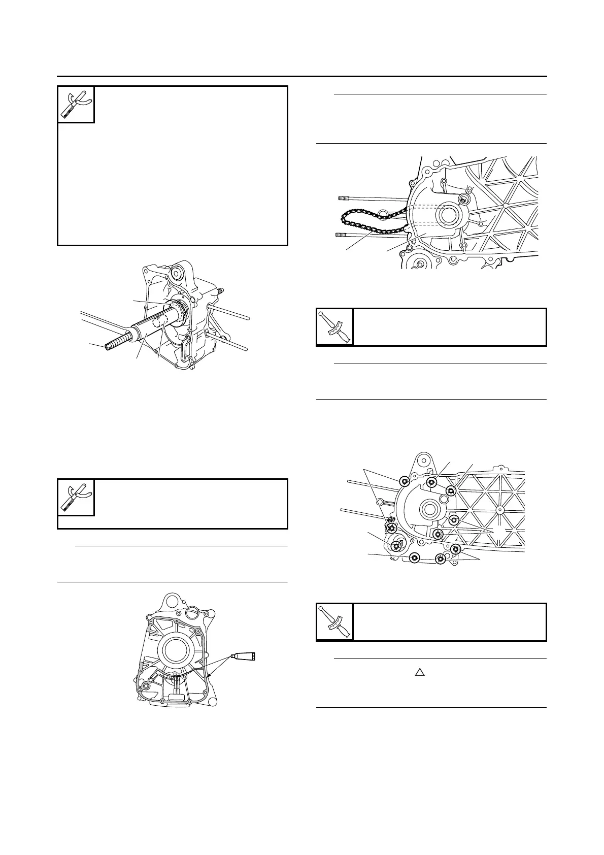
3. Install:
• Timing chain “1”
• Left crankcase “2”
IP
After installing the left crankcase, make sure that
the timing chain is securely meshed with the
crankshaft sprocket.
4. Install:
• Crankcase bolts
IP
Tighten the crankcase bolts in stages and in a
crisscross pattern.
• M6 × 110 mm (4.33 in) bolts: “1”
• M6 × 80 mm (3.15 in) bolts: “2”
• M6 × 70 mm (2.76 in) bolts: “3”
5. Install:
• Oil filter element cover “1”
IP
Be sure to face the “” mark “a” on the oil filter
element cover in the direction shown in the illus-
tration.
Crankshaft installer pot
90890-01274
Installing pot
YU-90058
Crankshaft installer bolt
90890-01275
Bolt
YU-90060
Adapter (M14)
90890-01478
Adapter #6
YM-90066
Yamaha bond No. 1215
90890-85505
(Three Bond No.1215®)
3
2
4
1
T
R
.
.
Crankcase bolt
10 Nm (1.0 m·kgf, 7.2 ft·lbf)
T
R
.
.
Oil filter element cover
10 Nm (1.0 m·kgf, 7.2 ft·lbf)
1
2
1
2
3
1
1
2
3
 Loading...