CYLINDER HEAD (YP125R)
5-9
EAS37P1002
REMOVING THE CYLINDER HEAD
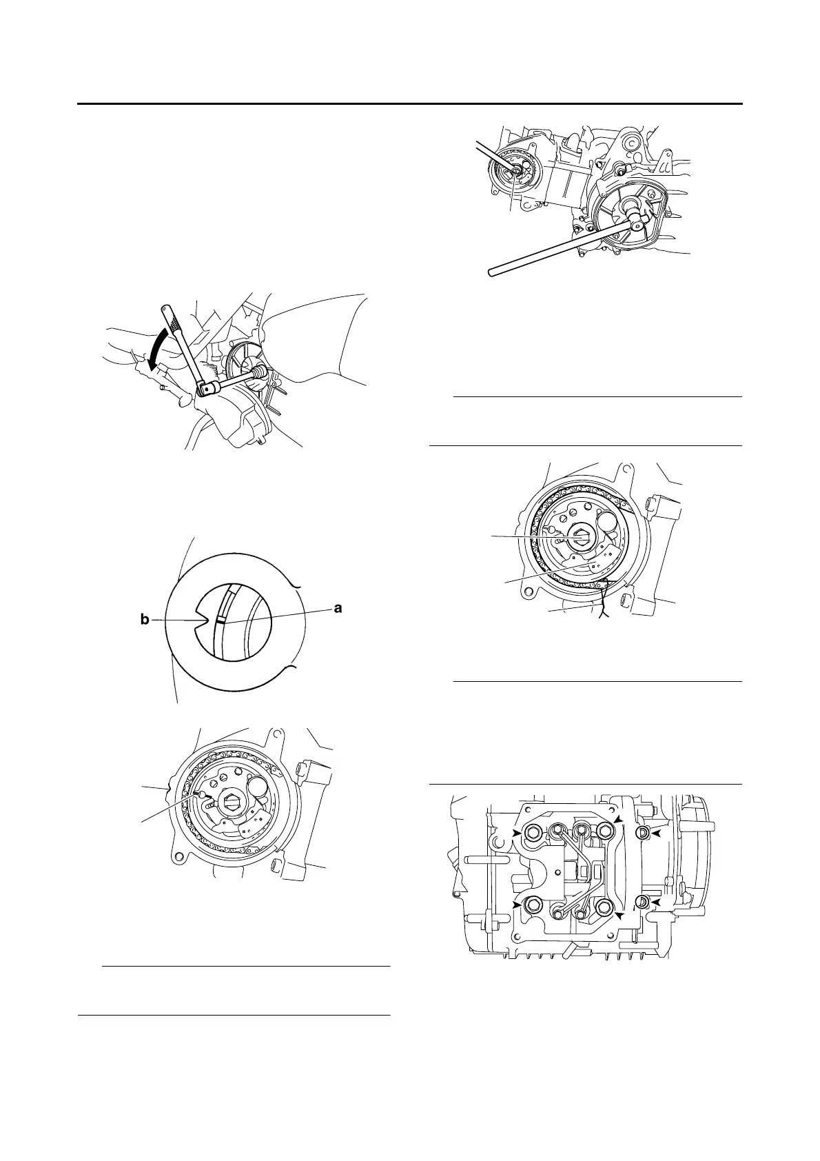
1. Align:
•“I” mark “a” on the generator rotor
(with the stationary pointer “b” on the genera-
tor cover)
▼▼▼▼▼▼▼▼▼ ▼ ▼▼▼▼▼▼▼▼▼ ▼ ▼▼▼▼ ▼ ▼▼▼▼ ▼▼▼
a. Turn the primary sheave nut on the left side
of the crankshaft counterclockwise to turn the
crankshaft.
b. When the piston is at TDC on the compres-
sion stroke, align the “I” mark “c” on the cam-
shaft sprocket with the stationary pointer “d”
on the cylinder head.
▲▲▲▲▲▲▲▲▲ ▲ ▲▲▲▲▲▲▲▲▲ ▲ ▲▲▲▲ ▲ ▲▲▲▲ ▲▲▲
2. Loosen:
• Camshaft sprocket bolt “1”
IP
While holding the primary sheave nut with a
wrench, remove the camshaft sprocket bolt.
3. Remove:
• Timing chain tensioner
(along with the gasket)
• Camshaft sprocket bolt “1”
• Camshaft sprocket “2”
IP
To prevent the timing chain from falling into the
crankcase, fasten it with a wire “3”.
4. Remove:
• Cylinder head
IP
• Loosen the bolts and nuts in the proper se-
quence as shown.
• Loosen each bolt and nut 1/2 of a turn at a
time. After all of the bolts and nuts are fully
loosened, remove them.
EAS37P1003
CHECKING THE CYLINDER HEAD
1. Eliminate:
• Combustion chamber carbon deposits
(with a rounded scraper)
d
c
1
3
1
2
1
3
6
5
2
4
 Loading...