ELECTRICAL COMPONENTS
8-77
Checking the condition of the bulb sockets
The following procedure applies to all of the bulb
sockets.
1. Check:
• Bulb socket (for continuity)
(with the pocket tester)
No continuity → Replace.
IP
Check each bulb socket for continuity in the
same manner as described in the bulb section,
however, note the following.
▼▼▼▼▼▼▼▼▼ ▼ ▼▼▼▼▼▼▼▼▼ ▼ ▼▼▼▼ ▼ ▼▼▼▼ ▼▼▼
a. Install a good bulb into the bulb socket.
b. Connect the pocket tester probes to the re-
spective leads of the bulb socket.
c. Check the bulb socket for continuity. If any of
the readings indicate no continuity, replace
the bulb socket.
▲▲▲▲▲▲▲▲▲ ▲ ▲▲▲▲▲▲▲▲▲ ▲ ▲▲▲▲ ▲ ▲▲▲▲ ▲▲▲
EAS28000
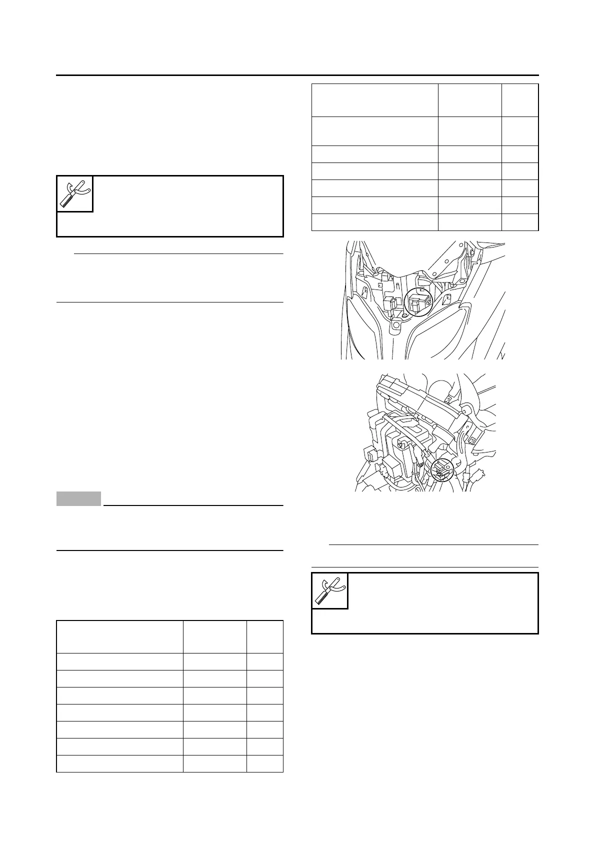
CHECKING THE FUSES
The fuse box, which contains the fuses for the in-
dividual circuits, is located behind the upper
panel. The main fuse and spare fuse (30.0 A)
are located behind the front cowling assembly.
NOTICE
ECA37P1040
To avoid a short circuit, always set the main
switch to “OFF” when checking or replacing
a fuse.
1. Remove:
• Upper panel and/or front cowling assembly
Refer to “GENERAL CHASSIS” on page 4-1.
2. Check:
• Fuse
▼▼▼▼▼▼▼▼▼ ▼ ▼▼▼▼ ▼ ▼▼▼▼ ▼ ▼▼▼▼ ▼ ▼▼▼▼ ▼▼▼
a. Connect the pocket tester to the fuse and
check the continuity.
IP
Set the pocket tester selector to “Ω × 1”.
b. If the pocket tester indicates “∞”, replace the
fuse.
▲▲▲▲▲▲▲▲▲ ▲ ▲▲▲▲ ▲ ▲▲▲▲ ▲ ▲▲▲▲ ▲ ▲▲▲▲ ▲▲▲
3. Replace:
• Blown fuse
▼▼▼▼▼▼▼▼▼ ▼ ▼▼▼▼ ▼ ▼▼▼▼ ▼ ▼▼▼▼ ▼ ▼▼▼▼ ▼▼▼
a. Set the main switch to “OFF”.
b. Install a new fuse of the correct amperage
rating.
Pocket tester
90890-03112
Analog pocket tester
YU-03112-C
Fuses
Amperage
rating
Q’ty
Main 30.0 A 1
Headlight 15.0 A 1
Signaling system 10.0 A 1
Ignition 10.0 A 1
Turn signal/hazard 10.0 A 1
Radiator fan motor 7.5 A 1
ECU 5.0 A 1
Backup (immobilizer
and meter assembly)
5.0 A 1
Spare 30.0 A 1
Spare 15.0 A 1
Spare 10.0 A 1
Spare 7.5 A 1
Spare 5.0 A 1
Pocket tester
90890-03112
Analog pocket tester
YU-03112-C
Fuses
Amperage
rating
Q’ty
 Loading...