FRONT BRAKE
4-27
EAS22530
INSTALLING THE FRONT BRAKE MASTER
CYLINDER
1. Install:
• Brake master cylinder “1”
• Brake master cylinder holder
IP
• Align the projection “a” on the brake master cyl-
inder with the hole “b” in the handlebar.
• First, tighten the front bolt, then the rear bolt.
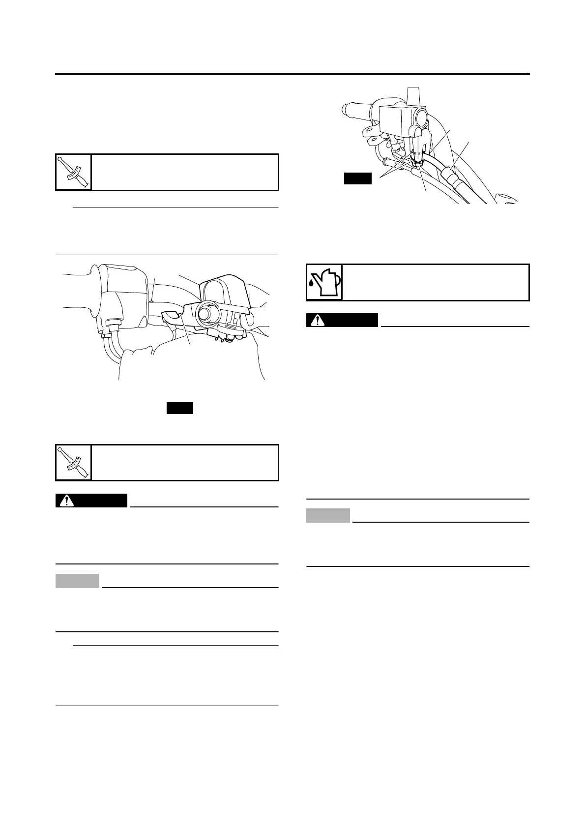
2. Install:
• Copper washers “1”
• Front brake hose “2”
• Brake hose union bolt “3”
WARNING
EWA37P1024
Proper brake hose routing is essential to in-
sure safe vehicle operation. Refer to “CABLE
ROUTING (YP125R)” on page 2-29 and “CA-
BLE ROUTING (YP250R)” on page 2-75.
NOTICE
ECA14160
When installing the brake hose onto the
brake master cylinder, make sure the brake
pipe touches the projection “a” as shown.
IP
Turn the handlebar to the left and right to make
sure the brake hose does not touch other parts
(e.g., wire harness, cables, leads). Correct if
necessary.
3. Fill:
• Brake master cylinder reservoir
(with the specified amount of the recom-
mended brake fluid)
WARNING
EWA13540
• Use only the designated brake fluid. Other
brake fluids may cause the rubber seals to
deteriorate, causing leakage and poor
brake performance.
• Refill with the same type of brake fluid that
is already in the system. Mixing brake fluids
may result in a harmful chemical reaction,
leading to poor brake performance.
• When refilling, be careful that water does
not enter the brake master cylinder reser-
voir. Water will significantly lower the boil-
ing point of the brake fluid and could cause
vapor lock.
NOTICE
ECA13540
Brake fluid may damage painted surfaces
and plastic parts. Therefore, always clean up
any spilt brake fluid immediately.
4. Bleed:
• Brake system
Refer to “BLEEDING THE HYDRAULIC
BRAKE SYSTEM” on page 3-36.
5. Check:
• Brake fluid level
Below the minimum level mark “a” → Add the
recommended brake fluid to the proper level.
Refer to “CHECKING THE BRAKE FLUID
LEVEL” on page 3-35.
T
R
.
.
Brake master cylinder holder bolt
7 Nm (0.7 m·kgf, 5.1 ft·lbf)
T
R
.
.
Brake hose union bolt
23 Nm (2.3 m·kgf, 17 ft·lbf)
b
1
a
New
Recommended fluid
DOT 4
1
3
a
2
New
 Loading...