FUEL INJECTION SYSTEM
8-33
EAS27350
ECU SELF-DIAGNOSTIC FUNCTION
The ECU is equipped with a self-diagnostic function in order to ensure that the fuel injection system is
operating normally. If this function detects a malfunction in the system, it immediately operates the en-
gine under substitute characteristics and illuminates the engine trouble warning light to alert the rider
that a malfunction has occurred in the system. Once a malfunction has been detected, a fault code is
stored in the memory of the ECU.
• To inform the rider that the fuel injection system is not functioning, the engine trouble warning light
flashes when the start switch is being pushed to start the engine.
• If a malfunction is detected in the system by the self-diagnostic function, the ECU provides an appro-
priate substitute characteristic operation, and alerts the rider of the detected malfunction by illuminat-
ing the engine trouble warning light.
• After the engine has been stopped, the lowest fault code number appears on the odometer LCD.
Once a fault code has been displayed, it remains stored in the memory of the ECU until it is deleted.
Engine trouble warning light indication and fuel injection system operation
* The warning light flashes when any one of the conditions listed below is present and the start switch
is pushed:
Checking for a defective engine trouble warning light
The engine trouble warning light comes on for 2.0 seconds after the main switch has been set to “ON”
and when the start switch is being pushed. If the warning light does not come on under these conditions,
the warning light bulb may be defective.
ECU detects an abnormal signal from a sensor
If the ECU detects an abnormal signal from a sensor while the vehicle is being driven, the ECU illumi-
nates the engine trouble warning light and provides the engine with alternate operating instructions that
are appropriate for the type of malfunction.
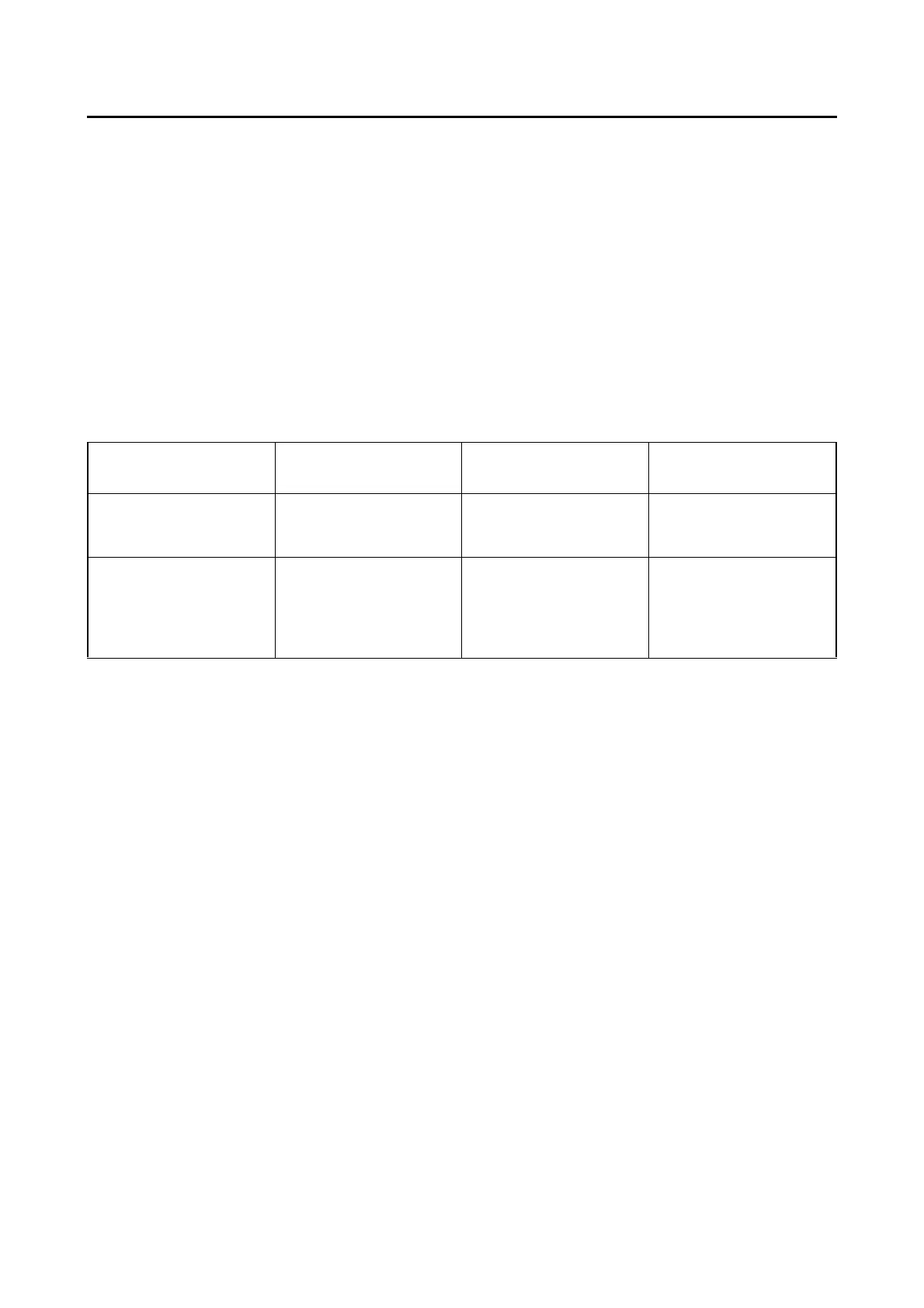
Warning light indica-
tion
ECU operation FI operation Vehicle operation
Flashing*
Warning provided
when unable to start
engine
Operation stopped Cannot be operated
Remains on Malfunction detected
Operated with substi-
tute characteristics in
accordance with the
description of the mal-
function
Can or cannot be oper-
ated depending on the
fault code
12: Crankshaft position sensor 30:
Lean angle sensor
(latch up detected)
13:
Intake air pressure sensor
(open or short circuit)
33: Faulty ignition
14:
Intake air pressure sensor
(clogged or detached hose)
39:
Fuel injector
(open or short circuit)
15:
Throttle position sensor
(open or short circuit)
41:
Lean angle sensor
(open or short circuit)
16:
Throttle position sensor
(stuck)
50:
ECU internal malfunction
(memory check error)
19:
Blue/yellow ECU lead
(broken or disconnected)
 Loading...