ELECTRICAL COMPONENTS
8-85
EAS28150
CHECKING THE STATOR COIL
1. Disconnect:
• Stator coil coupler
(from the wire harness)
2. Check:
• Stator coil resistance
Out of specification → Replace the crank-
shaft position sensor/stator assembly.
▼▼▼▼▼▼▼▼▼ ▼ ▼▼▼▼▼▼▼▼▼ ▼ ▼▼▼▼ ▼ ▼▼▼▼ ▼▼▼
a. Connect the pocket tester (Ω × 1) to the stator
coil coupler as shown.
b. Measure the stator coil resistance.
▲▲▲▲▲▲▲▲▲ ▲ ▲▲▲▲▲▲▲▲▲ ▲ ▲▲▲▲ ▲ ▲▲▲▲ ▲▲▲
EAS28170
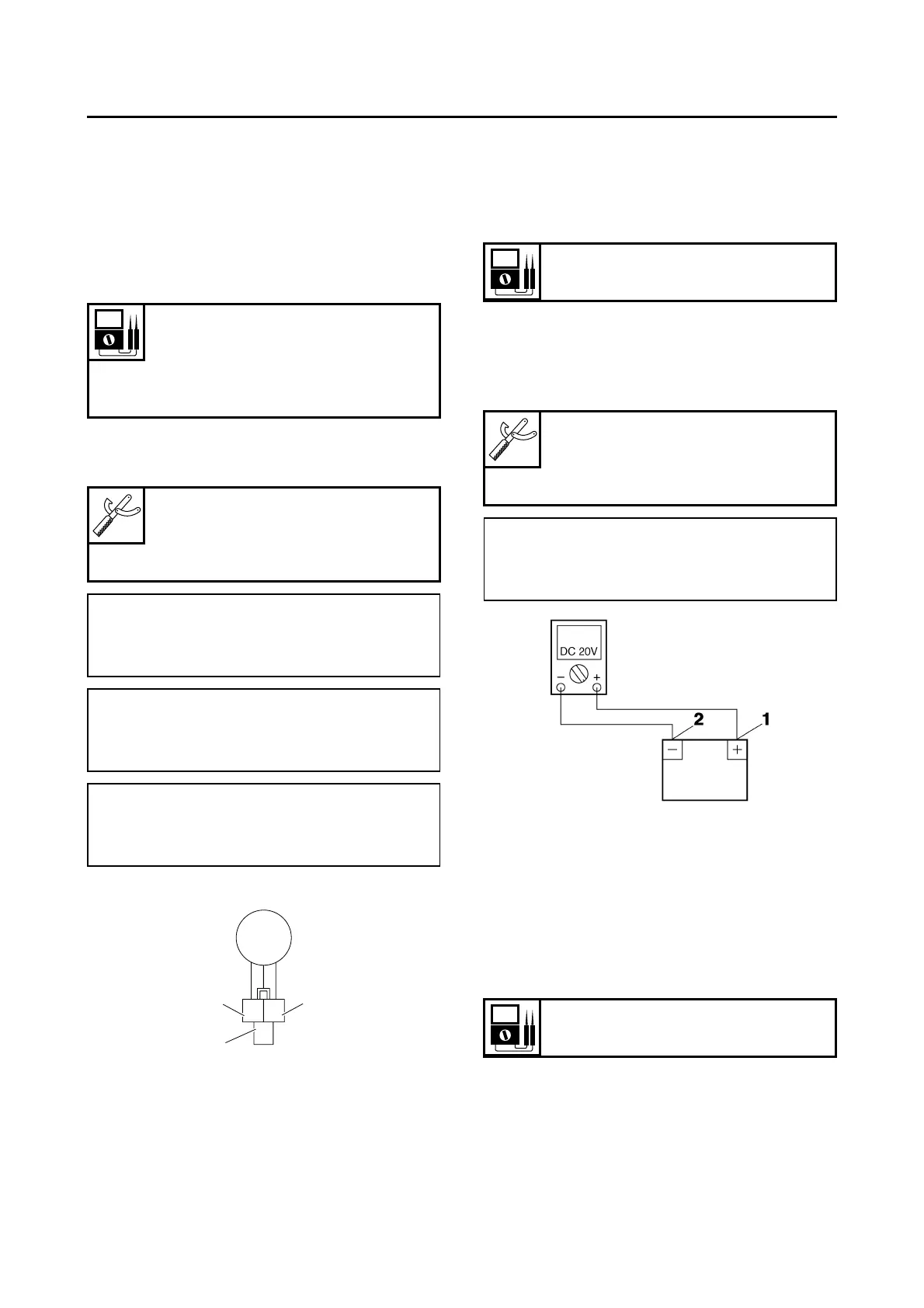
CHECKING THE RECTIFIER/REGULATOR
1. Check:
• Charging voltage
Out of specification → Replace the rectifi-
er/regulator.
▼▼▼▼▼▼▼▼▼ ▼ ▼▼▼▼ ▼ ▼▼▼▼ ▼ ▼▼▼▼ ▼ ▼▼▼▼ ▼▼▼
a. Connect the engine tachometer to the spark
plug lead.
b. Connect the pocket tester (DC 20 V) to the
battery as shown.
c. Start the engine and let it run at approximate-
ly 5000 r/min.
d. Measure the charging voltage.
▲▲▲▲▲▲▲▲▲ ▲ ▲▲▲▲ ▲ ▲▲▲▲ ▲ ▲▲▲▲ ▲ ▲▲▲▲ ▲▲▲
EAS28180
CHECKING THE HORN
1. Check:
• Horn resistance
Out of specification → Replace.
▼▼▼▼▼▼▼▼▼ ▼ ▼▼▼▼ ▼ ▼▼▼▼ ▼ ▼▼▼▼ ▼ ▼▼▼▼ ▼▼▼
a. Disconnect the horn connectors from the
horn terminals.
b. Connect the pocket tester (Ω × 1) to the horn
terminals.
Stator coil resistance
0.28–0.42 Ω at 20 °C (68 °F)
(YP125R)
0.32–0.48 Ω at 20 °C (68 °F)
(YP250R)
Pocket tester
90890-03112
Analog pocket tester
YU-03112-C
• Positive tester probe →
white “1”
• Negative tester probe →
white “2”
• Positive tester probe →
white “1”
• Negative tester probe →
white “3”
• Positive tester probe →
white “2”
• Negative tester probe →
white “3”
1
2
3
WW
W
Charging voltage
14 V at 5000 r/min
Pocket tester
90890-03112
Analog pocket tester
YU-03112-C
• Positive tester probe →
positive battery terminal “1”
• Negative tester probe →
negative battery terminal “2”
Coil resistance
1.4 Ω at 20 °C (68 °F)
 Loading...