ELECTRICAL COMPONENTS
8-88
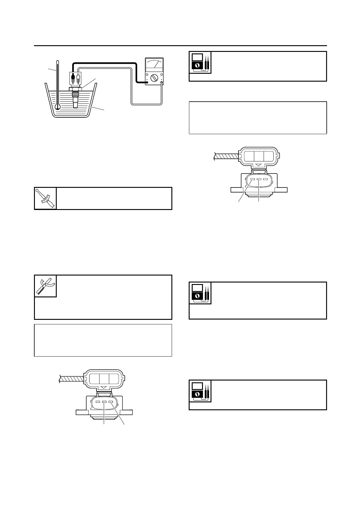
d. Heat the coolant or let it cool down to the
specified temperatures.
e. Measure the coolant temperature sensor re-
sistances.
▲▲▲▲▲▲▲▲▲ ▲ ▲▲▲▲▲▲▲▲▲ ▲ ▲▲▲▲ ▲ ▲▲▲▲ ▲▲▲
3. Install:
• Coolant temperature sensor
EAS28300
CHECKING THE THROTTLE POSITION
SENSOR
1. Check:
• Throttle position sensor
▼▼▼▼▼▼▼▼▼ ▼ ▼▼▼▼▼▼▼▼▼ ▼ ▼▼▼▼ ▼ ▼▼▼▼ ▼▼▼
a. Connect the digital circuit tester to the throttle
position sensor as shown.
b. Measure the throttle position sensor voltage.
Out of specification → Replace or repair the
wire harness.
c. Connect the digital circuit tester to the throttle
position sensor as shown.
d. While slowly opening the throttle, check that
the throttle position sensor voltage is in-
creased.
Voltage does not change or it changes
abruptly → Replace the throttle position sen-
sor.
Out of specification (closed position) → Re-
place the throttle position sensor.
▲▲▲▲▲▲▲▲▲ ▲ ▲▲▲▲ ▲ ▲▲▲▲ ▲ ▲▲▲▲ ▲ ▲▲▲▲ ▲▲▲
EAS28410
CHECKING THE INTAKE AIR PRESSURE
SENSOR
1. Check:
• Intake air pressure sensor output voltage
Out of specification → Replace.
▼▼▼▼▼▼▼▼▼ ▼ ▼▼▼▼ ▼ ▼▼▼▼ ▼ ▼▼▼▼ ▼ ▼▼▼▼ ▼▼▼
a. Connect the test harness between the intake
air pressure sensor and wire harness.
b. Connect the pocket tester (DC 20 V) to the
test harness.
T
R
.
.
Coolant temperature sensor
18 Nm (1.8 m·kgf, 13 ft·lbf)
Digital circuit tester
90890-03174
Model 88 Multimeter with ta-
chometer
YU-A1927
• Positive tester probe →
gray/red “1”
• Negative tester probe →
gray/black “2”
3
1
2
Y
Gy/RGy/B
21
Throttle position sensor voltage
5 V
(gray/red–gray/black)
• Positive tester probe →
yellow “1”
• Negative tester probe →
gray/black “2”
Throttle position sensor voltage
(closed position)
0.40–0.90 V
(yellow–gray/black)
Intake air pressure sensor output
voltage
3.57–3.71 V
Y
Gy/RGy/B
2
1
 Loading...