CRANKSHAFT (YP250R)
5-115
EAS25960
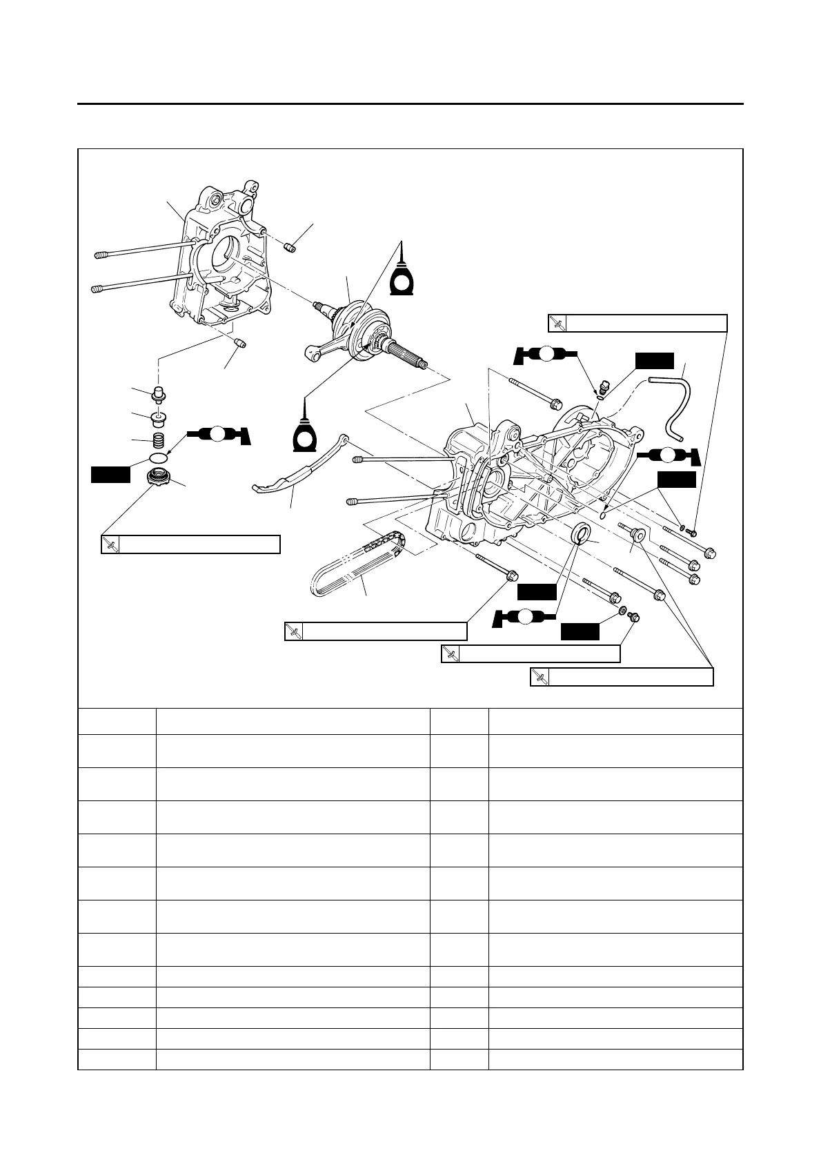
CRANKSHAFT (YP250R)
Removing the crankshaft
Order Job/Parts to remove Q’ty Remarks
Water pump assembly
Refer to “WATER PUMP (YP250R)” on page
6-12.
Engine
Refer to “ENGINE REMOVAL (YP250R)” on
page 5-61.
Cylinder head
Refer to “CYLINDER HEAD (YP250R)” on
page 5-67.
Piston
Refer to “CYLINDER AND PISTON
(YP250R)” on page 5-84.
Belt drive
Refer to “V-BELT AUTOMATIC TRANSMIS-
SION (YP250R)” on page 5-89.
Oil pump assembly
Refer to “OIL PUMP (YP250R)” on page
5-108.
Transmission
Refer to “TRANSMISSION (YP250R)” on
page 5-112.
1 Transmission case breather hose 1
2 Oil strainer cover 1
3Spring 1
4 Oil strainer 1
5 Breather pipe 1
New
New
2
7
11
13
6
1
12
3
4
5
9
9
LS
LS
E
E
LS
8
10
New
New
New
LS
10 Nm (1.0 m
•
kgf, 7.2 ft
•
Ibf)
T
.R.
10 Nm (1.0 m
•
kgf, 7.2 ft
•
Ibf)
T
.R.
20 Nm (2.0 m
•
kgf, 14 ft
•
Ibf)
T
.R.
22 Nm (2.2 m
•
kgf, 16 ft
•
Ibf)
T
.R.
32 Nm (3.2 m
•
kgf, 23 ft
•
Ibf)
T
.R.
 Loading...