CAMSHAFT (YP125R)
5-15
EAS37P1008
REMOVING THE CAMSHAFT
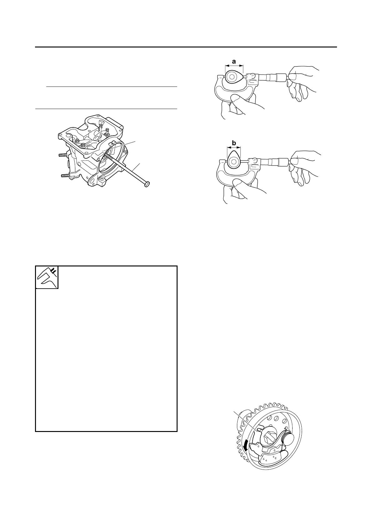
1. Remove:
• Camshaft “1”
IP
Screw an M8 bolt “2” into the threaded end of the
camshaft, and then pull out the camshaft.
EAS37P1009
CHECKING THE CAMSHAFT
1. Check:
• Camshaft lobes
Blue discoloration/pitting/scratches → Re-
place the camshaft.
2. Measure:
• Camshaft lobe dimensions “a” and “b”
Out of specification → Replace the camshaft.
3. Check:
• Camshaft oil passage
Obstruction → Blow out with compressed air.
EAS37P1010
CHECKING THE DECOMPRESSION SYSTEM
1. Check:
• Decompression system
▼▼▼▼▼▼▼▼▼ ▼ ▼▼▼▼ ▼ ▼▼▼▼ ▼ ▼▼▼▼ ▼ ▼▼▼▼ ▼▼▼
a. Check the decompression system with the
camshaft sprocket and the decompression
cam installed to the camshaft.
b. Check that the decompression lever “1”
moves smoothly.
c. Without operating the decompression lever,
check that the decompression cam “2”
projects from the camshaft (exhaust cam) as
shown in the illustration “A”.
d. Move the decompression lever in the direc-
tion of the arrow shown and check that the
decompression cam does not project from
the camshaft (exhaust cam) as shown in the
illustration “B”.
Camshaft lobe dimensions
Intake A
30.225–30.325 mm (1.1900–
1.1939 in)
Limit
30.125 mm (1.1860 in)
Intake B
25.064–25.164 mm (0.9868–
0.9907 in)
Limit
24.964 mm (0.9828 in)
Exhaust A
30.261–30.361 mm (1.1914–
1.1953 in)
Limit
30.161 mm (1.1874 in)
Exhaust B
25.121–25.221 mm (0.9890–
0.9930 in)
Limit
25.021 mm (0.9851 in)
1
2
1
 Loading...