ELECTRICAL COMPONENTS
8-86
c. Measure the horn resistance.
▲▲▲▲▲▲▲▲▲ ▲ ▲▲▲▲▲▲▲▲▲ ▲ ▲▲▲▲ ▲ ▲▲▲▲ ▲▲▲
EAS28230
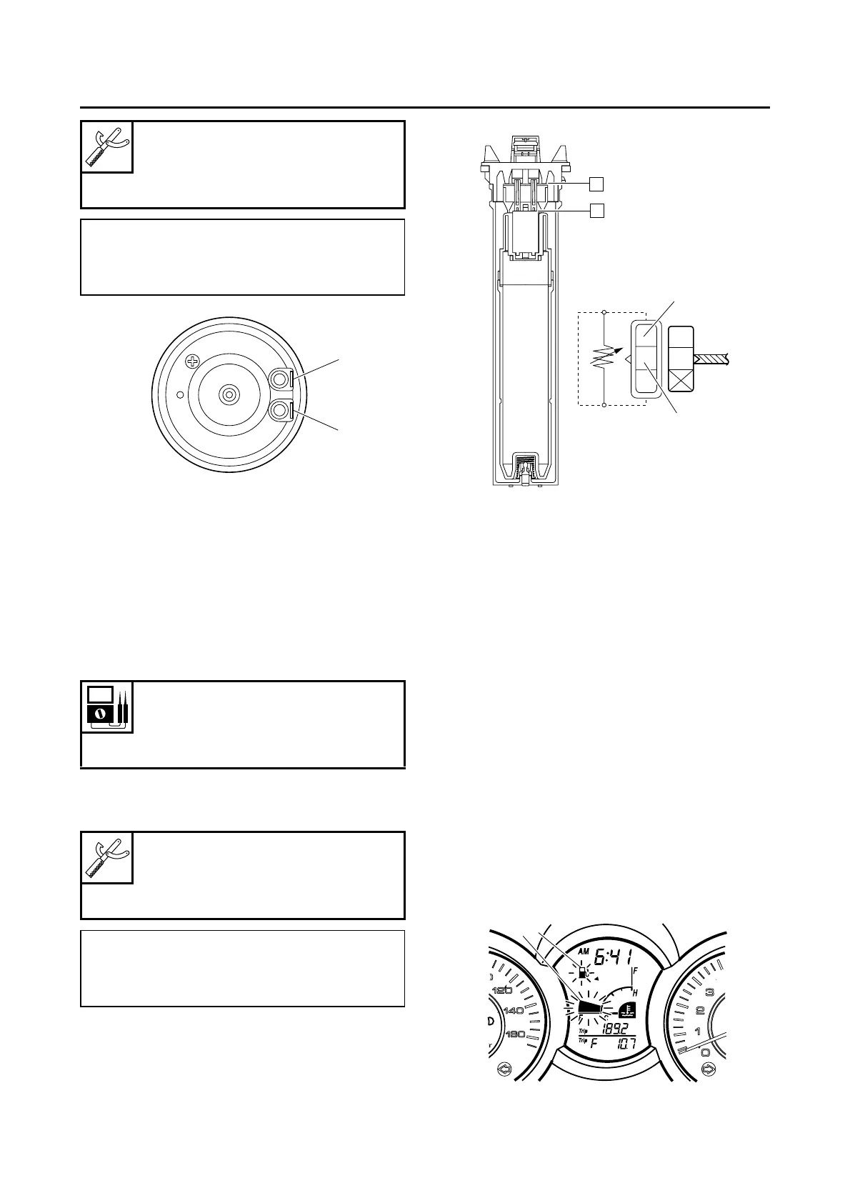
CHECKING THE FUEL SENDER
1. Remove:
• Fuel sender
2. Check:
• Fuel sender resistance
Out of specification → Replace the fuel send-
er.
▼▼▼▼▼▼▼▼▼ ▼ ▼▼▼▼▼▼▼▼▼ ▼ ▼▼▼▼ ▼ ▼▼▼▼ ▼▼▼
a. Connect the pocket tester (Ω × 10) to the fuel
sender terminal as shown.
b. Measure the fuel sender resistance.
▲▲▲▲▲▲▲▲▲ ▲ ▲▲▲▲ ▲ ▲▲▲▲ ▲ ▲▲▲▲ ▲ ▲▲▲▲ ▲▲▲
EAS29040
CHECKING THE FUEL LEVEL WARNING
LIGHT
This model is equipped with a self-diagnosis de-
vice for the fuel level detection circuit.
1. Check:
• Fuel level warning light “1”
(Set the main switch to “ON”.)
The warning light comes on for a few sec-
onds, then goes off → The warning light is
OK.
The warning light does not come on → Re-
place the meter assembly.
All LCD segments of the fuel meter “2” and
the fuel level warning light “1” flash (open or
short circuit detected in fuel sender) → Re-
place the fuel sender.
Pocket tester
90890-03112
Analog pocket tester
YU-03112-C
• Positive tester probe →
horn terminal “1”
• Negative tester probe →
horn terminal “2”
Sender unit resistance (full)
20.0 Ω
Sender unit resistance (empty)
140.0 Ω
Pocket tester
90890-03112
Analog pocket tester
YU-03112-C
• Positive tester probe →
sky blue “1”
• Negative tester probe →
black “2”
1
2
A. Full fuel tank position
B. Empty fuel tank position
Sb
B
A
B
2
1
1
2
 Loading...