WATER PUMP (YP125R)
6-7
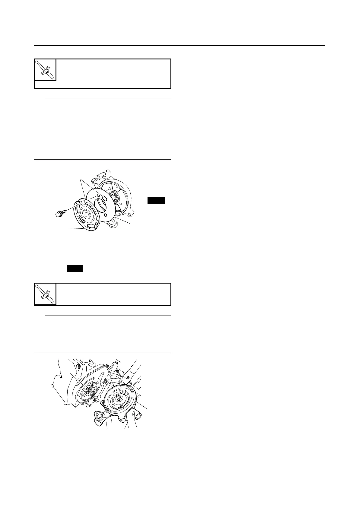
• Water pump housing plate 1 “3”
IP
• After installation, check that the impeller shaft
rotates smoothly.
• Be sure to align the bolt holes in the water
pump housing plate gasket and water pump
housing plates. Make sure that the gasket
does not block the holes “a” in the water pump
housing plates.
EAS37P1115
INSTALLING THE WATER PUMP
1. Install:
• O-rings
• Water pump assembly “1”
IP
• Lubricate the O-rings with a thin coat of lithium-
soap-based grease.
• Align the projection “a” on the impeller shaft
with the slot “b” in the camshaft sprocket bolt.
2. Fill:
• Cooling system
(with the specified amount of the recom-
mended coolant)
Refer to “CHANGING THE COOLANT” on
page 3-18.
3. Check:
• Cooling system
Leaks → Repair or replace any faulty part.
T
R
.
.
Water pump housing plate 1 bolt
10 Nm (1.0 m·kgf, 7.2 ft·lbf)
LOCTITE®
T
R
.
.
Water pump assembly bolt
10 Nm (1.0 m·kgf, 7.2 ft·lbf)
New
a
1
2
3
New
a
b
1
 Loading...