3-105
Confidential
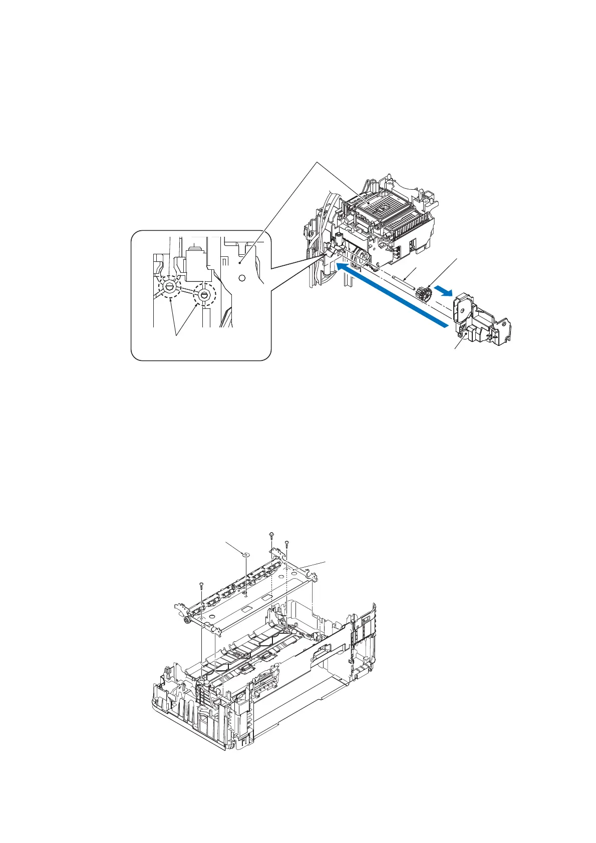
Assembling Note: Attach the Drive unit, using the following steps.
1) Attach the Shaft and Gear to the Drive unit.
2) After aligning the two Shafts with the D cutouts in the Maintenance unit, attach the Drive
unit to the Maintenance unit.
Fig. 3-120
9.47 Inner Chute ASSY
(1) Release the wiring of the Registration sensor PCB ASSY.
(2) Remove the screw (TAPTITE CUP B M3x10) and the two screws (TAPTITE BIND
B M3x10).
(3) Remove the Frame base stopper ring, lift up the rear end of the Frame base, and
take it off the Lower cover.
Fig. 3-121
Maintenance unit
D cutouts
(Align with Shafts)
Gear
Shaft
Drive unit
Frame base
stopper ring
Frame base
TAPTITE BIND B M3x10
TAPTITE CUP B M3x10
TAPTITE BIND B M3x10
 Loading...