TS-12 Musician’s Manual Section 9 — Program Parameters
13
velocity, etc. You can create some very interesting filter configurations by using a different
modulator for each filter. For instance, try using pressure to modulate the filters. You can drive
one filter up with pressure, while simultaneously driving the other down.
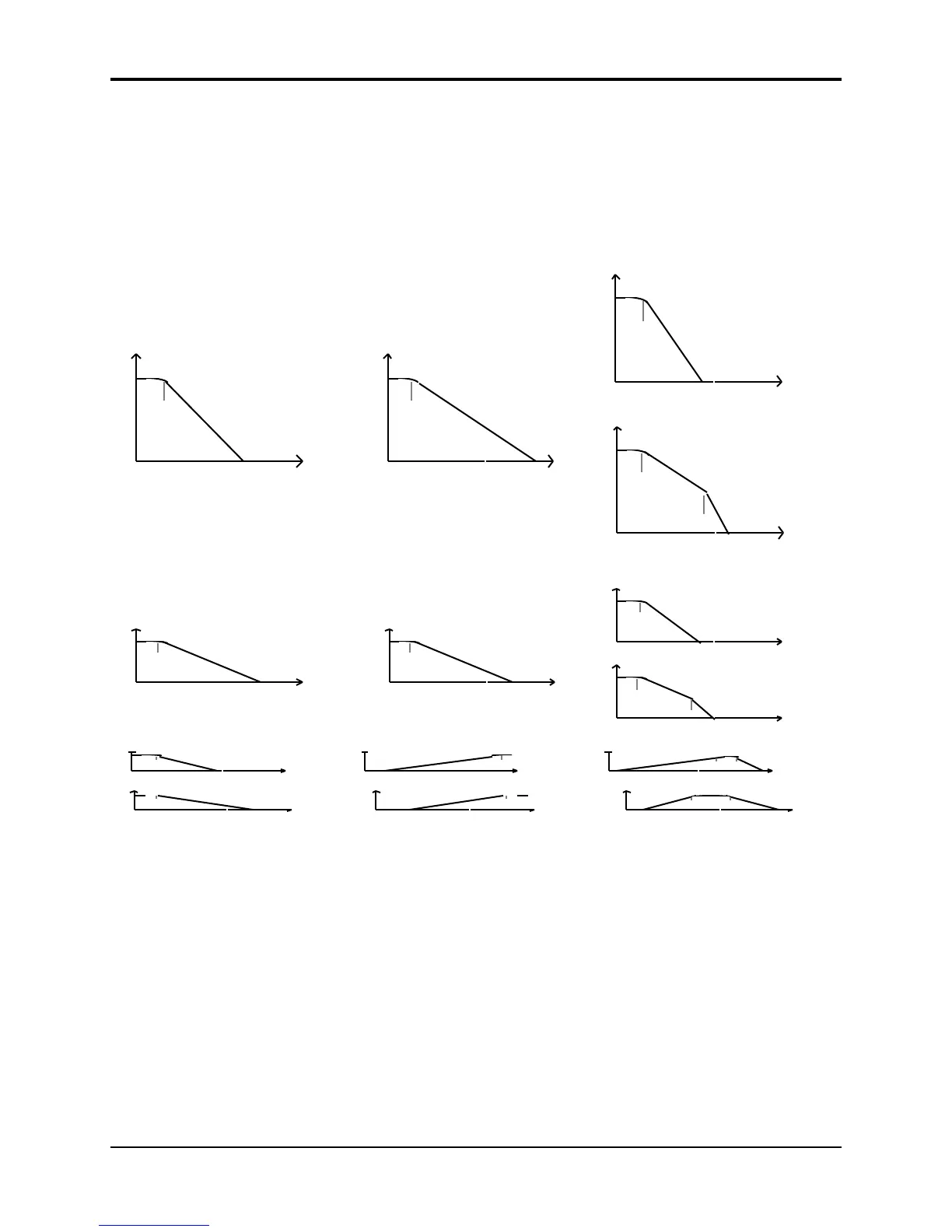
Filter Configurations
The diagrams below show a number of possible filter configurations. On the left are the response
curves of the two filters shown separately. On the right are some of the possible shapes of the
combined filters.
amplitude
frequency0
freq.
cutoff
18 db / oct
Filter 1 = 3 pole / Low-pass
amplitude
frequency0
freq.
cutoff
24 db / oct
4 pole / Low-pass
amplitude
frequency0
freq.
cutoff
6 db / oct
Filter 2 = 1 pole / Low-pass
amplitude
frequency0
freq.
cutoff #2
freq.
cutoff #1
6 db / oct
24 db / oct
4 pole / Low-pass
+ = Or
+
=
amplitude
frequency0
freq.
cutoff
12 db / oct amplitude
frequency0
freq.
cutoff
12 db / oct
Filter 2 = 2 pole / Low-passFilter 1 = 2 pole / Low-pass
amplitude
frequency0
24 db / oct
freq.
cutoff
4 pole / Low-pass
(when F1 & 2 are
tuned to the same
freq.)
amplitude
frequency0
freq.
cutoff #1
freq.
cutoff #2
12 db / oct
24 db / oct
4 pole / Low-pass
Or
F F
Filter 1 = 3/LP Filter 2 = 1/HP Bandpass
+
=
+ =
F F
BandpassFilter 1 = 2 pole / Low-pass Filter 2 = 2 pole / High-pass
FILTER 1 Page
Press the Filters button. The display shows the FILTER1 page.
 Loading...