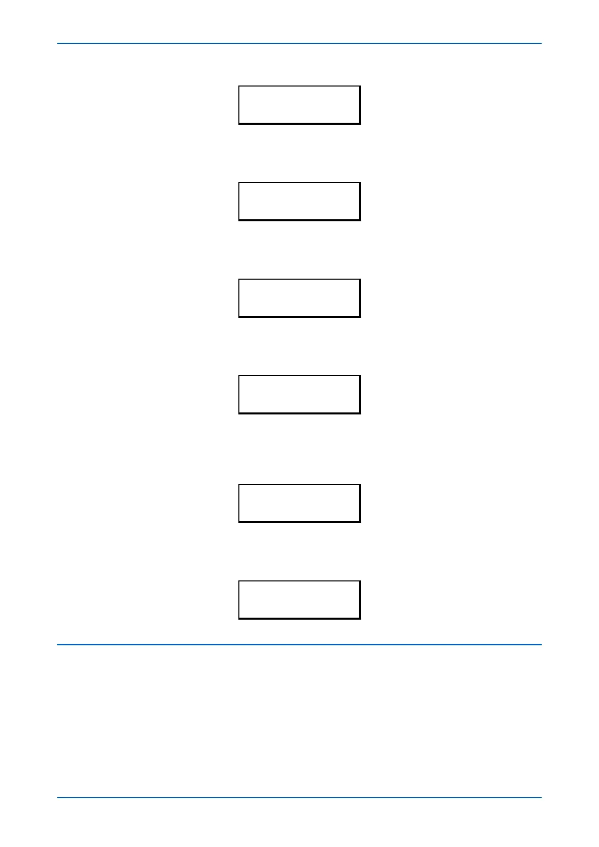
COMMUNICATIONS
RP1 Inactivtimer
10.00 mins.
6. If the optional fibre optic connectors are fitted, the RP1 PhysicalLink cell is visible. This cell contr
ols the
physical media used for the communication (Copper or Fibre optic).
COMMUNICATIONS
RP1 PhysicalLink
Copper
7. Move down to the next cell (RP1 Car
d Status). This cell is not settable. It displays the status of the chosen
physical layer protocol for RP1.
COMMUNICATIONS
RP1 Card Status
K-Bus OK
8. Move down to the next cell (RP1 P
ort Config). This cell controls the type of serial connection. Select between
K-Bus or RS485.
COMMUNICATIONS
RP1 Port Config
K-Bus
9. If using EIA(RS)485, the next cell (RP1 Comms Mode) selects the communication mode. The choice is either
IEC 60870 F
T1.2 for normal operation with 11-bit modems, or 10-bit no parity. If using K-Bus this cell will not
appear.
COMMUNICATIONS
RP1 Comms Mode
IEC 60870 FT1.2
10. If using EIA(RS)485, the next cell down controls the baud rate. Three baud rates are supported; 9600, 19200
and 38400. If using K-Bus this cell will not appear as the baud rate is fixed at 64
kbps.
COMMUNICATIONS
RP1 Baud rate
19200
3.2 DNP3 CONFIGURATION
To configure the device:
1.
Select the CONFIGURATION column and check that the Comms settings cell is set to Visible.
2. Select the COMMUNICATIONS column.
3. Move to the first cell down (RP1 protocol). This is a non-settable cell, which shows the chosen
communication protocol – in this case DNP3.0.
P64x Chapter 5 - Configuration
P64x-TM-EN-1.3 89

 Loading...


