5 APPLICATION NOTES
5.1 STAR WINDING RESISTANCE EARTHED
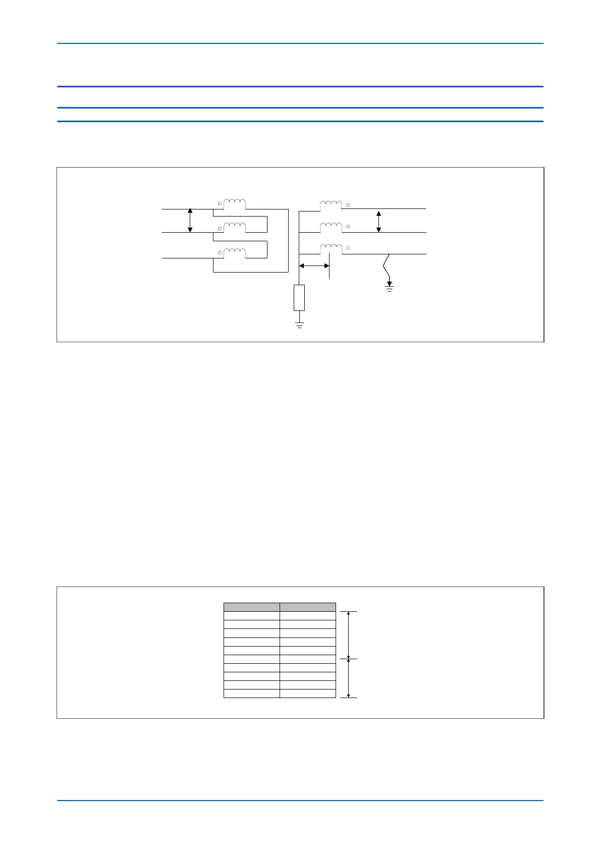
Consider the following resistance earthed star winding below.
a
b
c
C
A
B
Primary
Secondary
x
V1
V2
V00681
Figure 81: Star winding, resistance earthed
An earth fault on such a winding causes a current which is dependent on the value of earthing impedance. This
earth fault current is proportional to the distance of the fault from the neutral point since the fault voltage is
directly proportional to this distance.
The ratio of transformation between the primary winding and the short circuited turns also varies with the position
of the fault. Therefore the current that flows through the transformer terminals is proportional to the square of the
fraction of the winding which is short circuited.
The earthing resistor is rated to pass the full load current I
FLC
= V1/Ö3R
Assuming that V1 = V2 then T2 = Ö3T1
For a fault at x PU distance from the neutral, the fault current If = xV1/Ö3R
Therefore the secondary fault current referred to the primary is I
primary
= x
2
.I
FLC
/Ö3
If the fault is a single end fed fault, the primary current should be greater than 0.2 pu (Is1 default setting) for the
differential protection to operate. Therefore x
2
/Ö3 > 20%
The following diagram shows that 41% of the winding is protected by the differential element.
X in %
V00682
Idiff in %
10 0.58
100
90
80
70
60
50
40
30
20
57.74
46.77
36.95
28.29
20.00
14.43
9.24
5.20
2.31
59% of unprotected winding
41% of unprotected winding
Figure 82: Percentage of winding protected
Chapter 8 - Restricted Earth Fault Protection P64x
178 P64x-TM-EN-1.3
 Loading...


