Is1 is set to 10% of the winding nominal curr
ent:
= (0.1 x 90 x 10
6
) / (
Ö
3 x 132 x 10
3
)
= 39 Amps primary
= 39/400 = 0.0975 Amps secondary (approx 0.1 A)
Is2 is set to the rated current of the transformer:
= 90 x 10
6
/ (
Ö
3 x 132 x 10
3
)
= 390 Amps primary
= 390/400 = 0.975 Amps secondary (approx 1 A)
Set K1 to 0% and K2 to 150%
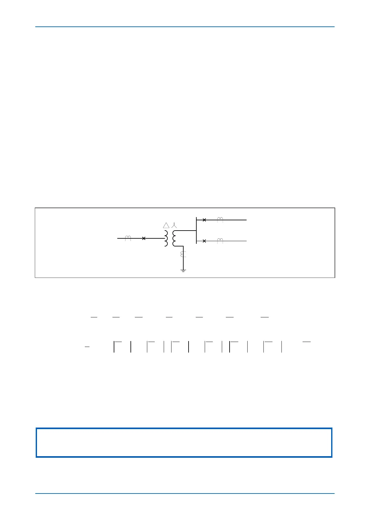
5.2.4 DUAL CB APPLICATION WITH DIFFERENT PHASE CT RATIOS
The following diagram shows the situation where low impedance REF is being used in a dual breaker (breaker-and-
a-half
) application where the phase CT ratios (CT
x
and CT
y
) are different. In this example, one phase of a
conventional transformer is shown, but the explanation is also applicable to autotransformers.
Figure 84: Low-Z REF for dual CB application with different phase CT ratios
The low impedance REF f
unction be used in dual breaker (breaker-and-a-half) applications. The line CT ratios can
be different. In this case the low impedance REF differential and bias current formulae are calculated as follows:
I IA IB IC K IA K IB K IC K I
diff REF
CTx CTx
CTx
CTy CTy
CTy
( )
= + + + + +
( )
+
1 1 1 2
NN
I IA K IA IB K IB IC K IC
bias REF
CTx CTy CTx CTy
CTx CT
( )
max= +
( )
+
( )
+
1
2
1 1 1
yy
K IN
( )
+
}
{
2
where:
● CT
x
and CT
y
(T1, T2, T3, T4 or T5) are the current inputs associated with a particular winding (given in the
settings HV CT Terminals, LV CT Terminals and TV CT Terminals respectively)
● K1 = CT
y
Ratio/CT
x
Ratio (Scaling Factor K1)
● K2 = Neutral CT Ratio/CT
x
Ratio (Scaling Factor K2)
● Reference: CT
x
.
Note:
The above formulae are valid for autotransformers and conventional transformers when the Phase CT Ratios are different
(CTx ≠ CTy) and the reference is CTx
Chapter 8 - Restricted Earth Fault Protection P64x
180 P64x-TM-EN-1.3

 Loading...


