V03112
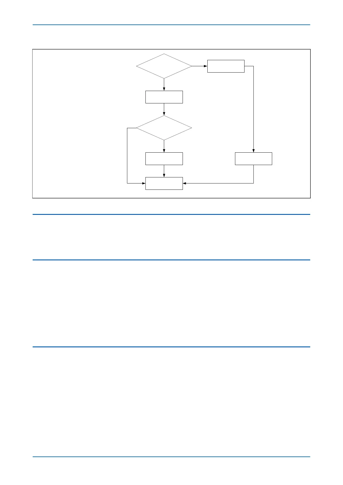
Any phase
I
diff(5 fn)/Idiff(fn) > Setting
Y
N
Counter + = 1
Counter = 0
Counter >= 2
Y
Block 1-phase
L
ow-set diff
N
Return
Drop-off
Figure 49: 5th harmonic blocking process
4.4 5TH HARMONIC SETTING GUIDELINE
In most applications, the default settings will ensure stability of the differential element. If more difficult situations
exist
, the 5th harmonic differential current blocking facility may be of use.
A typical setting for Ih(5)%> is 35%.
4.5 GEOMAGNETIC DISTURBANCES
To offer protection against damage due to persistent overfluxing caused by a geomagnetic disturbance, the 5th
harmonic block
ing element can be mapped to an output contact using an associated timer. Operation of this
element could be used to give an alarm to the network control centre. If such alarms are received from a number
of transformers, they could serve as a warning of geomagnetic disturbance so that operators could take some
action to safeguard the power system.
Alternatively this element can be used to initiate tripping in the event of prolonged pick up of a 5th harmonic
measuring element. It is not expected that this type of overfluxing condition would be detected by the AC
overfluxing protection. This form of time delayed tripping should only be applied in regions where geomagnetic
disturbances are a known problem and only after proper evaluation through simulation testing.
4.6 OVERALL HARMONIC BLOCKING LOGIC
The following logic diagram shows how the differential protection blocking mechanism works under conditions of
ov
erfluxing and magnetisation inrush.
P64x Chapter 6 - Transformer Differential Protection
P64x-TM-EN-1.3 119
 Loading...


