2.1.4 DIFFERENCES BETWEEN THE NORTH AMERICAN AND EUROPEAN STANDARDS
The IEEE and US curves are set differently to the IEC/UK curves, with regard to the time setting. A time multiplier
setting (TMS) is used to adjust the operating time of the IEC cur
ves, whereas a time dial setting is used for the
IEEE/US curves. The menu is arranged such that if an IEC/UK curve is selected, the I> Time Dial cell is not visible
and vice versa for the TMS setting. For both IEC and IEEE/US type curves, a definite time adder setting is available,
which will increase the operating time of the curves by the set value.
2.2 PRINCIPLES OF IMPLEMENTATION
The range of protection products provides a very wide range of protection functionality. Despite the diverse range
of f
unctionality provided, there is some commonality between the way many of the protection functions are
implemented. It is important to describe some of these basic principles before going deeper into the individual
protection functions.
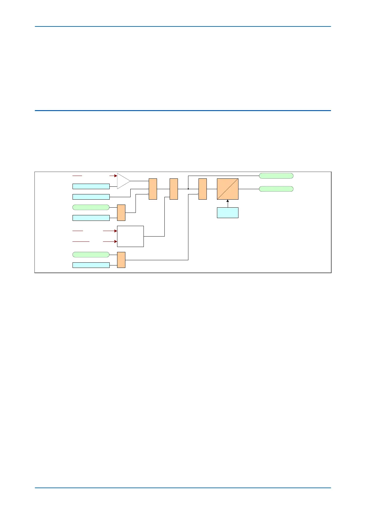
A simple representation of protection functionality is shown in the following diagram:
&
Start signal
Trip Signal&
Timer Blocking signals
1
V00654
Timer Settings
Threshold
IDMT/ DT
Timer Blocking settings
Stage Blocking signals
1
Stage Blocking settings
Function inhibit
Directional Check
&
Energising quantity
Voltage
Current
Figure 92: Principle of protection function implementation
An ener
gising quantity is either a voltage input from a system voltage transformer, a current input from a system
current transformer or another quantity derived from one or both of these. The energising quantities are extracted
from the power system. The signals are converted to digital quantities where they can be processed by the IEDs
internal processor.
In general, an energising quantity, be it a current, voltage, power, frequency, or phase quantity, is compared with a
threshold value, which may be settable, or hard-coded depending on the function. If the quantity exceeds (for
overvalues) or falls short of (for undervalues) the threshold, a signal is produced, which when gated with the
various inhibit and blocking functions becomes the Start signal for that protection function. This Start signal is
generally made available to Fixed Scheme Logic (FSL) and Programmable Scheme Logic (PSL) for further
processing. It is also passed through a timer function to produce the Trip signal. The timer function may be an
IDMT curve, or a Definite Time delay, depending on the function. This timer may also be blocked with timer
blocking signals and settings. The timer can be configured by a range of settings to define such parameters as the
type of curve, The Time Multiplier Setting, the IDMT constants, the Definite Time delay etc.
In GE products, there are usually several independent stages for each of the functions, and for three-phase
functions, there are usually independent stages for each of the three phases.
Typically some stages use an Inverse Definite Minumum time (IDMT) timer function, and others use a Definite Time
timer (DT) function. If the DT time delay is set to '0', then the function is known to be "instantaneous". In many
instances, the term 'instantaneous protection" is used loosely to describe Definite Time protection stages, even
when the stage may not theoretically be instantaneous.
Many protection functions require a direction-dependent decision. Such functions can only be implemented where
both current and voltage inputs are available. For such functions, a directional check is required, whose output can
block the Start signal should the direction of the fault be wrong.
P64x Chapter 9 - Current Protection Functions
P64x-TM-EN-1.3 199

 Loading...


