V01225
All Poles Dead
IA
VTS I> Inhibit
IB
VTS I> Inhibit
IC
VTS I> Inhibit
1
VAB
VBC
V2
Hardcoded threshold
I2
I2>1 Current Set
Delta IA
Delta IB
Delta IC
Hardcoded threshold
Hardcoded threshold
Hardcoded threshold
Any Pole Dead
VTS Reset Mode
Manual
Auto
MCB/VTS
VTS Status
Indication
Blocking
VTS Acc Ind
&
&
1
&
&
&1
S
R
Q
1
&
S
R
Q
1
&
VTS Slow Block
VTS Fast Block
VT Fail Alarm
&1
&
&
1
S
R
Q
1
Hardcoded threshold
Hardcoded threshold
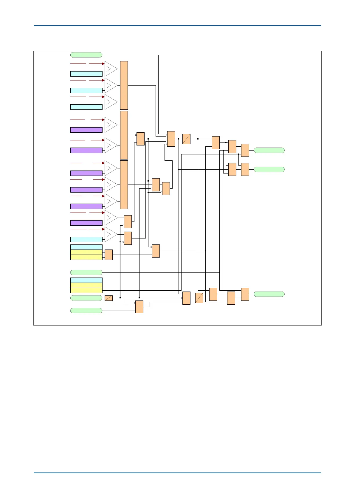
Note: This diagram does not show all stages . Other stages follow similar principles.
Figure 132: VTS logic (P643 and P645 with 3-phase VTs)
For the P643 and P645, a 3-phase V
T is used and each of the input voltages VA, VB and VC are with respect to
earth. For the P642, two single-phase VTs are used and the two input voltages VA and VB are phase-to-phase
voltages
As can be seen from the diagram, the VTS function is inhibited if:
● An All Poles Dead DDB signal is present
● A phase overcurrent condition exists
● A Negative Phase Sequence current exists
● If the phase current changes over the period of 1 cycle
The VTS will operate if:
● All three of the input voltages are lower than the VTS Pickup threshold AND the function is not inhibited by
any of the above criteria
● Negative Sequence Voltage is present AND the function is not inhibited by any of the above criteria
P64x Chapter 14 - Supervision
P64x-TM-EN-1.3 289

 Loading...


