Note:
The opt
o-input circuitry can be provided without the A/D circuitry as a separate board, which can provide supplementary
opto-inputs.
6.5.2 FREQUENCY RESPONSE
With the exception of the RMS measurements, all other measurements and protection functions are based on the
Fourier
-derived fundamental component. The fundamental component is extracted by using a 24 sample Discrete
Fourier Transform (DFT). This gives good harmonic rejection for frequencies up to the 23rd harmonic. The 23rd is
the first predominant harmonic that is not attenuated by the Fourier filter and this is known as an ‘Alias’. However,
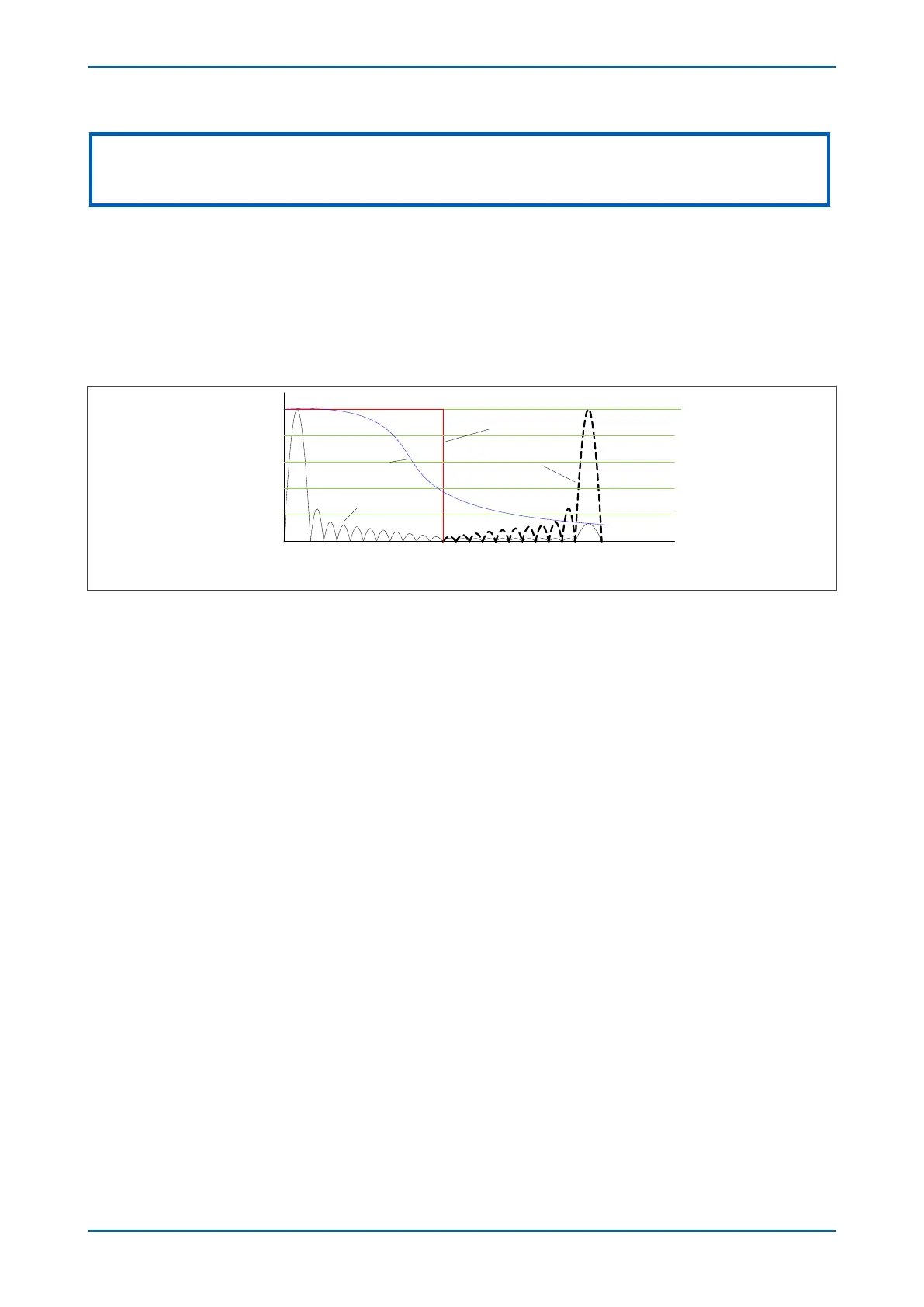
the Alias is attenuated by approximately 85% by an additional, analogue, ‘anti-aliasing’ filter (low pass filter). The
combined affect of the anti-aliasing and Fourier filters is shown below.
Ideal anti-alias filter response
Real anti-alias filter
response
2 3 4
1
0.2
0.4
0.6
0.8
5 6 7 8 9 10 11 12 13 14 15 16 17 18 19 20 21 22 23 241
50 Hz 600 Hz
1200 Hz
V00301
Fourier response without
anti-alias filter
Fourier response with
anti-alias filter
Alias frequency
Figure 18: Frequency response
For pow
er frequencies that are not equal to the selected rated frequency, the harmonics are attenuated to zero
amplitude. For small deviations of +/-1 Hz, this is not a problem but to allow for larger deviations, frequency
tracking is used.
Frequency tracking automatically adjusts the sampling rate of the analog to digital conversion to match the
applied signal. In the absence of a suitable signal to amplitude track, the sample rate defaults to the selected rated
frequency (Fn). If the a signal is in the tracking range of 45 to 66 Hz, the relay locks onto the signal and the
measured frequency coincides with the power frequency. The outputs for harmonics up to the 23rd are zero. The
device frequency tracks off any voltage or current in the order VA/VB/VC/IA/IB/IC down to 10% Vn for voltage and
5%In for current.
Chapter 3 - Hardware Design P64x
48 P64x-TM-EN-1.3

 Loading...


