5.2 LOW IMPEDANCE REF PROTECTION APPLICATION
5.2.1 SETTING GUIDELINES FOR BIASED OPERATION
Two bias settings are provided in the REF characteristic. The K1 level of bias is applied up to through currents of
Is2, which is normally set to the rated curr
ent of the transformer. K1 is normally be set to 0% to give optimum
sensitivity for internal faults. However, if any CT mismatch is present under normal conditions, then K1 may be
increased accordingly, to compensate. We recommend a setting of 20% in this case.
K2 bias is applied for through currents above Is2 and would typically be set to 150%.
According to ESI 48-3 1977, typical settings for the Is1 thresholds are 10-60% of the winding rated current when
solidly earthed and 10-25% of the minimum earth fault current for a fault at the transformer terminals when
resistance earthed.
5.2.2 LOW IMPEDANCE REF SCALING FACTOR
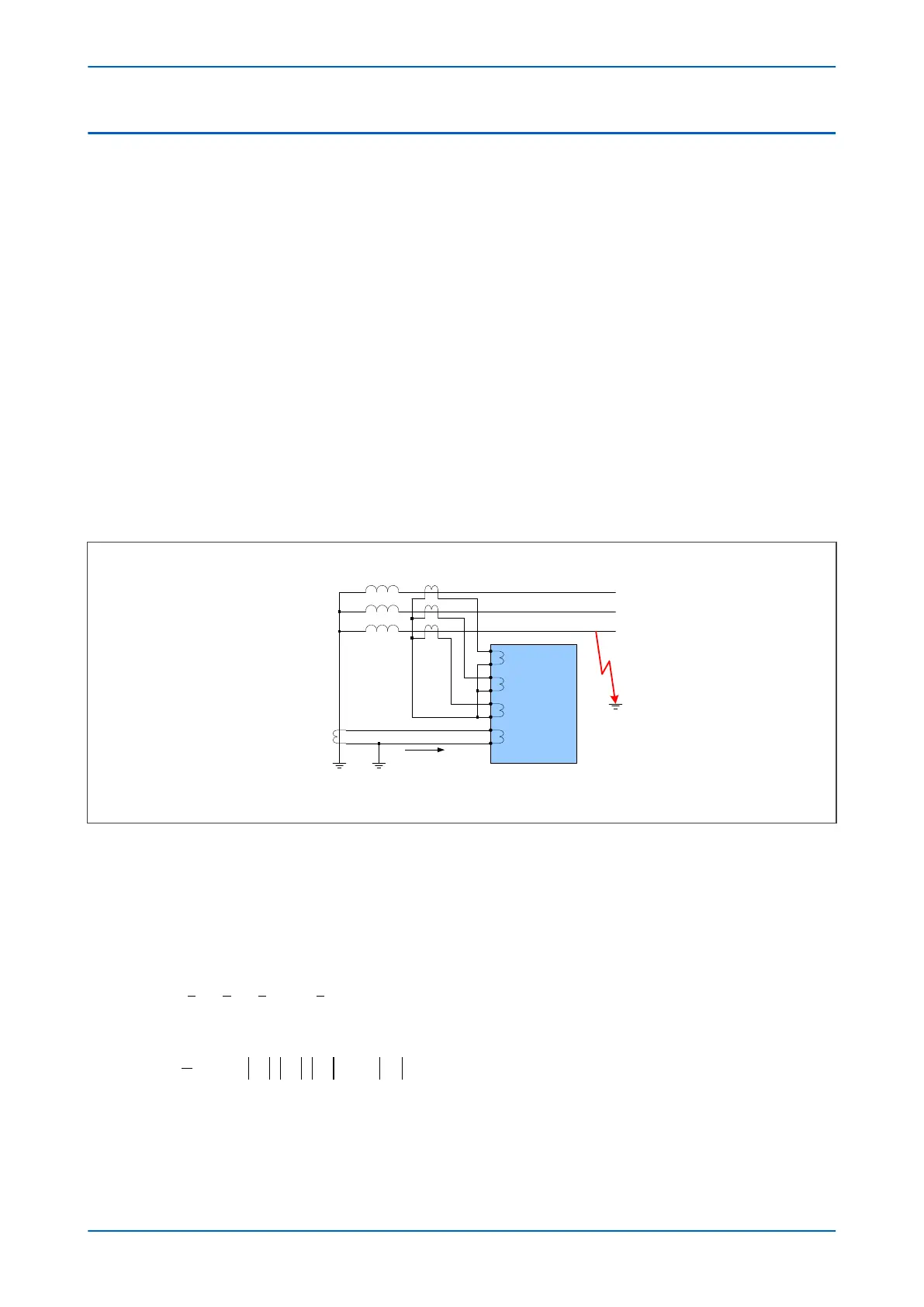
The three line CTs are connected to the three-phase CTs, and the neutral CT is connected to the neutral CT input.
These curr
ents are then used internally to derive both a bias and a differential current quantity for use by the low
impedance REF protection. The advantage of this mode of connection is that the line and neutral CTs are not
differentially connected, so the neutral CT can also be used to provide the measurement for the Standby Earth
Fault Protection. Also, no external components such as stabilizing resistors or Metrosils are required.
IED
V00683
I
Phase A
I
Phase B
I
Phase C
I
Neutral
Phase A
Phase B
Phase C
Line CTs 1000:1
Neutral CT 200:1
I
N
Figure 83: Low Impedance REF Scaling Factor
Another advantage of Low Impedance REF protection is that you can use a neutral CT with a lower ratio than the
line CTs in order to provide better earth fault sensitivity. In the bias calculation, the device applies a scaling factor
to the neutral current. This scaling factor is as follows:
Scaling factor = K = Neutral CT ratio / Line CT ratio
This results in the following differential and bias current equations:
I I I I KI
diff
A B C N
= + +
( )
+
I I I I K I
bias A B C N
=
+
{ }
1
2
max , ,
5.2.3 PARAMETER CALCULATIONS
Consider a solidly earthed 90 MVA transformer with a REF-protected star winding. Assume line CTS with a ratio of
400:1.
P64x Chapter 8 - Restricted Earth Fault Protection
P64x-TM-EN-1.3 179

 Loading...


