a
b
c
A
B
C
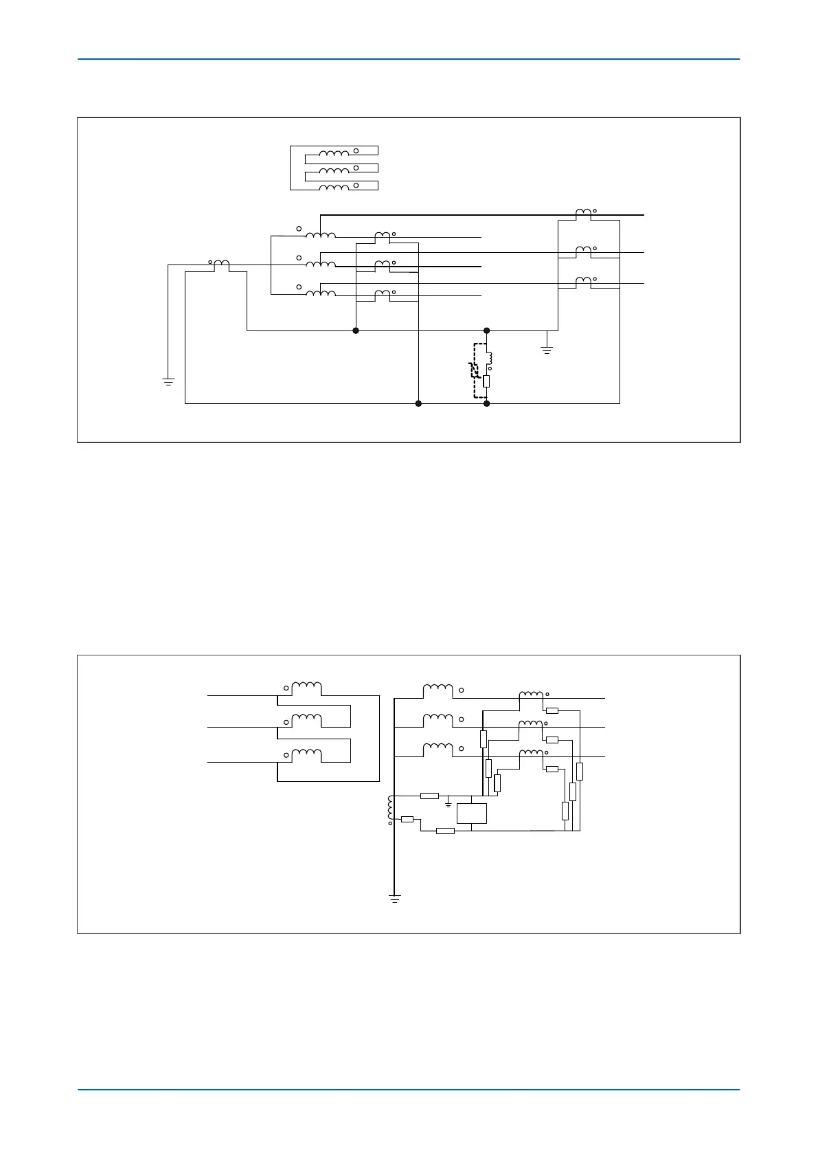
CT1
CT2
Varistor
Rst
TN1 CT
CTN
V00686
Figure 88: Hi-Z REF Protection for autotransformer configuration
5.3.2 SETTING GUIDELINES FOR HIGH IMPEDANCE OPERATION
This scheme is very sensitive and can protect against low levels of fault current in resistance grounded systems. In
this application, the IREF>Is settings should be chosen to pr
ovide a primary operating current less than 10-25% of
the minimum earth fault level.
This scheme can also be used in a solidly grounded system. In this application, the IREF>Is settings should be
chosen to provide a primary operating current between 10% and 60 % of the winding rated current.
The following diagram shows the application of a high impedance REF element to protect the LV winding of a
power transformer.
a
b
c
C
A
B
High Z
REF
R
L
R
CT
R
L
R
L
R
L
R
CT
Transformer:
90 MVA
33/132 kV
Dyn11, X = 5%
Buderns:
R
CT
= 0.5 W
R
L
= 0.98 W
400:1
V00687
Figure 89: High Impedance REF for the LV winding
5.3.2.1 STABILITY VOLTAGE CALCULATION
The transformer full load current, IFLC, is:
I
FL
C
= (90 x 10
6
) / (132 x 103 x
Ö
3) = 394 A
P64x Chapter 8 - Restricted Earth Fault Protection
P64x-TM-EN-1.3 185
 Loading...


