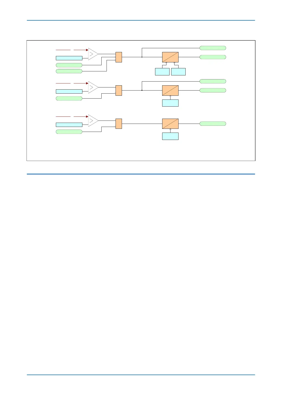
V/f
V/Hz>1 Trip Set
3ph V/Hz>1 Trip
V00867
Freq Not found
Blk 3ph V/ Hz>1
&
IDMT
3ph V/Hz>1 Start
V/f
V/Hz>1 Trip Set
3ph V/Hz>1 Trip
Freq Not found
&
DT
3ph V/Hz>1 Start
Note: The diagram is for a 3-phase VT. The logic for a 1-phase VT is the same .
This diagram does not show all stages . Other stages follow similar principles.
V/f
V/Hz Alarm Set
3Ph V/Hz> Alarm
Freq Not found
&
DT
V/Hz>1 Trip
TMS
V/Hz>1
Delay
V/Hz>1 Delay
V/Hz Alarm
Delay
Figure 119: Overfluxing protection logic
2.2 APPLICATION NOTES
2.2.1 OVERFLUXING PROTECTION SETTING GUIDELINES
The pick up value for the overfluxing elements depends on the nominal core flux density levels. Unit transformers
generally run at higher flux densities than transmission and distribution transformers, so they require a higher pick
up setting and shorter tripping times which reflect this. Transmission transformers can also be at risk from
overfluxing conditions, and you should take withstand levels into consideration when deciding on the required
settings.
The IEEE C37.91-2000 standard states that overexcitation of a transformer can occur whenever the ratio of the per
unit voltage to per unit frequency (V/Hz) at the secondary terminals of a transformer exceeds its rating of 1.05 per
unit (PU) on transformer base at full load, 0.8 power factor, or 1.1 PU at no load.
Please refer to clause 4.1.6 in IEEE C57.12.00-2006 for further clarification on the capability of a transformer to
operate above rated voltage and below rated frequency.
The element is set in terms of the actual ratio of voltage to frequency. You can therefore calculate the overfluxing
threshold setting V/Hz>(n) Trip Set, as follows:
A setting of 1.05 p.u. would equate to 110/50 x 1.05 = 2.31
where:
● The VT secondary voltage at rated primary volts is 110 V
● The rated frequency is 50 Hz
You should set the overfluxing alarm stage threshold V/Hz Alarm Set, lower than the trip stage setting, to provide
an indication that abnormal conditions are present and to alert an operator to adjust system parameters
accordingly.
You should choose the time delay settings to match the withstand characteristics of the protected transformer. For
an inverse time characteristic, set the time multiplier setting, V/Hz>1 Trip TMS such that the operating
characteristic closely matches the withstand characteristic of transformer. For definite time trip stages, set the
time delay V/Hz>(n) Trip Delay cells. The alarm stage time delay is set in the V/Hz Alarm Delay cell.
P64x Chapter 12 - Frequency Protection Functions
P64x-TM-EN-1.3 257
 Loading...


