6.2 NON-DIRECTIONAL EARTH FAULT LOGIC
&
EF 1 IN>1 TBlk
EF1 IN>1 Start
EF1 IN>1 Trip
&
EF1 IH2 Start
IN> Blocking
V00690
2H Blocks IN>1
IN
CTS Block
IN>1 Current
&
IDMT/ DT
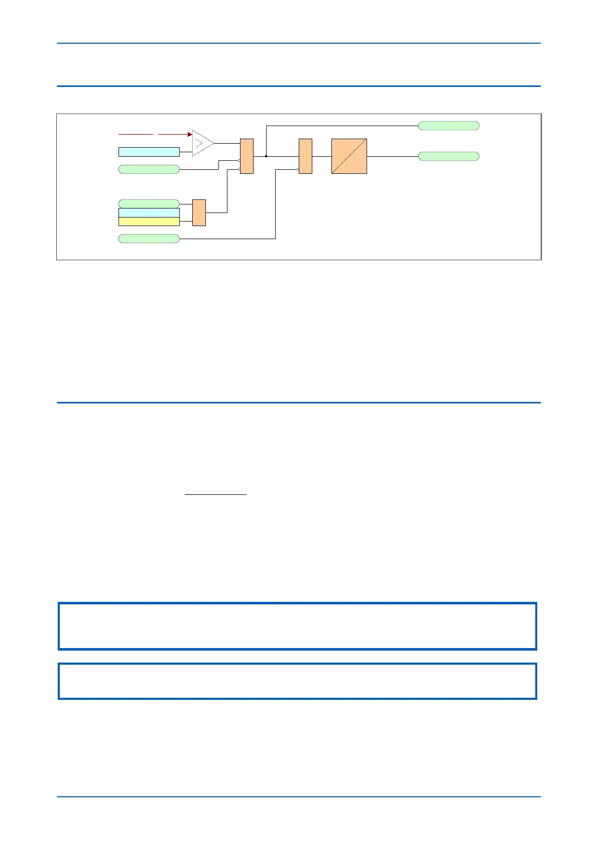
Figure 101: Non-directional EF logic (single stage)
The Ear
th Fault current is compared with a set threshold for each stage of each element. If it exceeds this
threshold, a Start signal is triggered, providing it is not blocked. This can be blocked by the second harmonic
blocking function, or an Inhibit Earth Fault DDB signal.
The timer can be blocked by the relevant timer block signal.
Earth Fault protection can follow the same IDMT characteristics as described in the Overcurrent Protection
Principles section. Please refer to this section for details of IDMT characteristics.
The diagram and description applies to all stages of all earth fault elements.
6.3 IDG CURVE
The IDG curve is commonly used for time delayed earth fault protection in the Swedish market. This curve is
available in stage 1 of the Earth Fault protection.
The IDG curve is represented by the following equation:
t
I
IN Setting
op e
= −
>
5 8 1 35. . log
where:
t
op
is the operating time
I is the measur
ed current
IN> Setting is an adjustable setting, which defines the start point of the characteristic
Note:
Although the start point of the characteristic is defined by the "ΙN>" setting, the actual current threshold is a different setting
called "IDG Ιs". The "IDG Ιs" setting is set as a multiple of "ΙN>".
Note:
When using an IDG Operat
e characteristic, DT is always used with a value of zero for the Rest characteristic.
An additional setting "IDG Time" is also used to set the minimum operating time at high levels of fault current.
P64x Chapter 9 - Current Protection Functions
P64x-TM-EN-1.3 217
 Loading...


