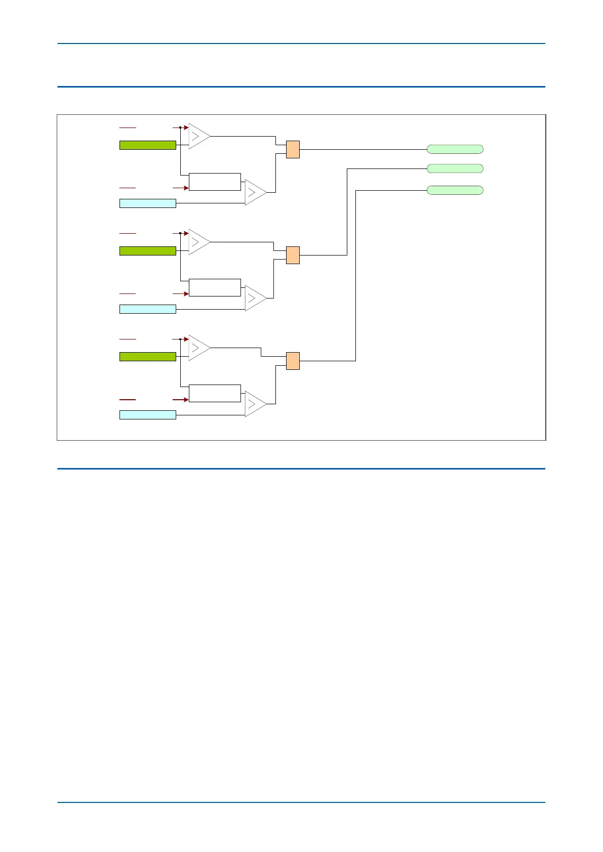
4.2 2ND HARMONIC BLOCKING LOGIC
Idiffa fundamental
Low current (hard-coded)
Idiffa 2
nd
harm / Idiffa fund
&
I2H Diff Set
IA2H Diff Start
IB2H Diff Start
IC2H Diff Start
&
I2H Diff Set
&
I2H Diff Set
Low current (hard-coded)
Low current (hard-coded)
I
diffa
2
nd
harmonic
I
diffb
fundamental
Idiffb 2
nd
harmonic
I
diffc
fundamental
I
diffc
2
nd
harmonic
I
diffb
2
nd
harm / I
diffb
fund
I
diffc
2
nd
harm / I
diffc
fund
V00706
Figure 48: 2nd harmonic blocking logic
4.3 5TH HARMONIC BLOCKING IMPLEMENTATION
The IED filters the differential current to determine the fundamental Idiff(fn) and the fifth harmonic component
Idiff(5fn). The device uses these quantities to pr
oduce a blocking signal, which will block the protection in the event
that the fifth harmonic component exceeds a certain level.
5th Harmonic blocking can be used to prevent unwanted operation of the low set differential element under
transient overfluxing conditions.
The 5th harmonic blocking threshold is adjustable between 0 - 100% differential current. The threshold should be
adjusted so that blocking will be effective when the magnetizing current rises above the chosen threshold setting
of the low-set differential protection.
Fifth harmonic blocking is phase segregated. If the ratio Idiff(5-fn)/Idiff(fn) exceeds an adjustable threshold (set by
I5H diff Set in two consecutive calculations, and if the differential current is larger than 0.1 pu (the minimum
setting of Is1), then the fifth harmonic blocking signal is issued for the relevant phase. The DDB signals are:
IA5H Diff Start (blocking signal for phase A)
IB5H Diff Start (blocking signal for phase B)
IC5H Diff Start (blocking signal for phase C)
No cross blocking is available for 5th harmonic blocking.
No blocking signal is asserted if the differential current exceeds the set thresholds Is-HS1 or Is-HS2.
The following flow diagram summarises the 5th harmonic blocking procedure:
Chapter 6 - Transformer Differential Protection P64x
118 P64x-TM-EN-1.3

 Loading...


