For Negative Phase Sequence Overcurrent Protection, the energising quanitity I2> is compar
ed with the threshold
voltage I2>1 Current Set. If the value exceeds this setting a start signal is generated, provided there are no blocks.
5% hysteresis is built into the comparator such that the drop-off value is 0.95 x of the current set threshold.
The function can be blocked by an Inhibit signal or by a CTS blocking signal.
The start signal is fed into a timer to produce the trip signal. The timer can be blocked by the timer block signal
This diagram and description applies to each stage of each element, where x is the number of the element and n
is the number of the stage.
5.3 DIRECTIONAL ELEMENT
Where negative phase sequence current may flow in either direction through an IED location, such as parallel lines
or ring main systems, dir
ectional control should be used.
Directionality is achieved by comparing the angle between the negative phase sequence voltage and the negative
phase sequence current. A directional element is available for all of the negative sequence overcurrent stages.
This is found in the I2>(n) Direction cell for the relevant stage for the relevant element. It can be set to non-
directional, directional forward, or directional reverse.
A suitable characteristic angle setting (I2> Char Angle) is chosen to provide optimum performance. This setting
should be set equal to the phase angle of the negative sequence current with respect to the inverted negative
sequence voltage (–V2), in order to be at the centre of the directional characteristic.
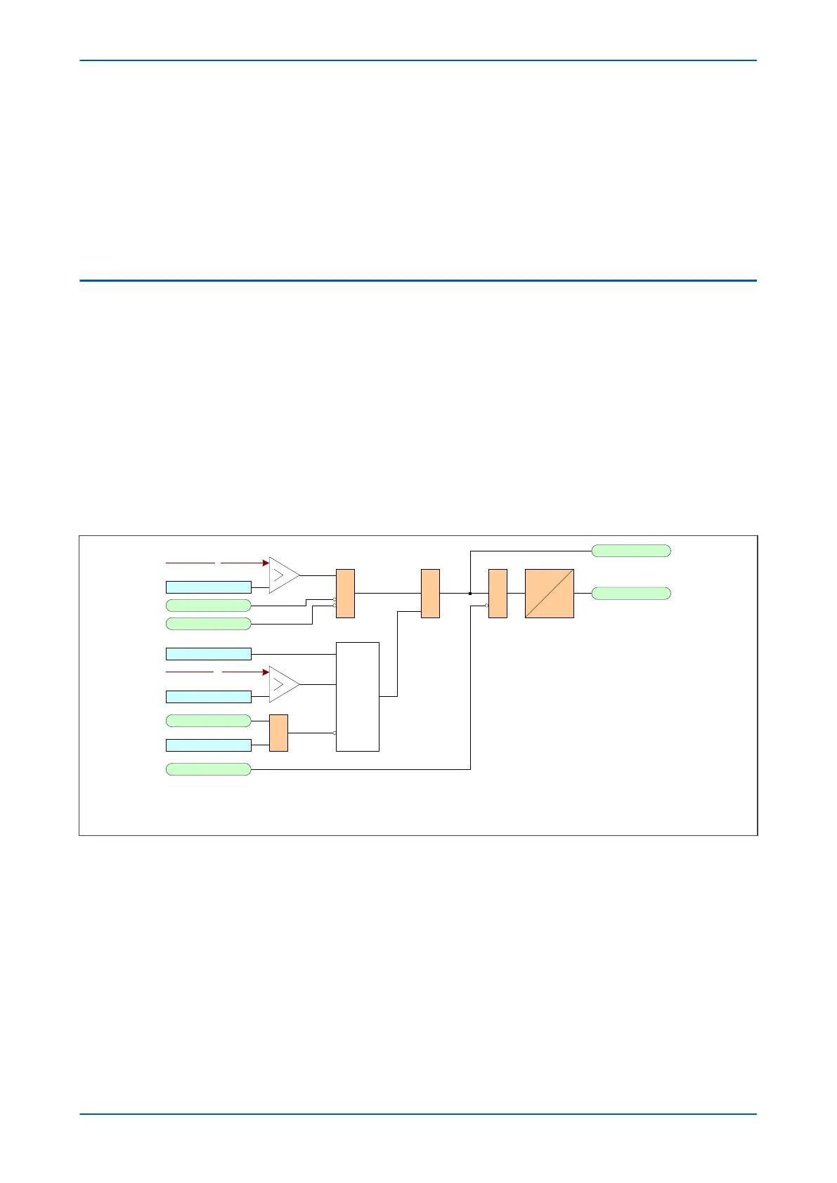
5.3.1 DIRECTIONAL NPSOC LOGIC
&
NPOC1 I2>1 TBlk
NPOC1 I2>1 Start
NPOC1 I2>1 Trip
&
V00675
I2
NPOC1 Inhibit
CTS Block
VTS Slow Block
I2> VTS Blocking
V2
I2>1 Current Set
I2> V2pol Set
&
IDMT/DT
Directional
check
&
I2>1 Direction
Note: This diagram does not show all stages . Other stages follow similar principles.
Figure 100: Negative Phase equence Overcurrent logic - directional operation
Directionality is achieved by comparing the angle between the negative phase sequence voltage and the negative
phase sequence current. The element may be selected to operate in either the forward or reverse direction. A
suitable characteristic angle setting (I2>Char Angle) is chosen to provide optimum performance. This setting
should be set equal to the phase angle of the negative sequence current with respect to the inverted negative
sequence voltage (–V2), in order to be at the centre of the directional characteristic.
For the negative phase sequence directional elements to operate, the device must detect a polarising voltage
above a minimum threshold, I2>V2pol Set. This must be set in excess of any steady state negative phase
sequence voltage. This may be determined during the commissioning stage by viewing the negative phase
sequence measurements in the device.
P64x Chapter 9 - Current Protection Functions
P64x-TM-EN-1.3 213
 Loading...


