CTs may be close to saturation so a high bias current is needed. More differential current is then needed to trip the
cir
cuit breakers, allowing greater security from external faults and less risk of maloperation.
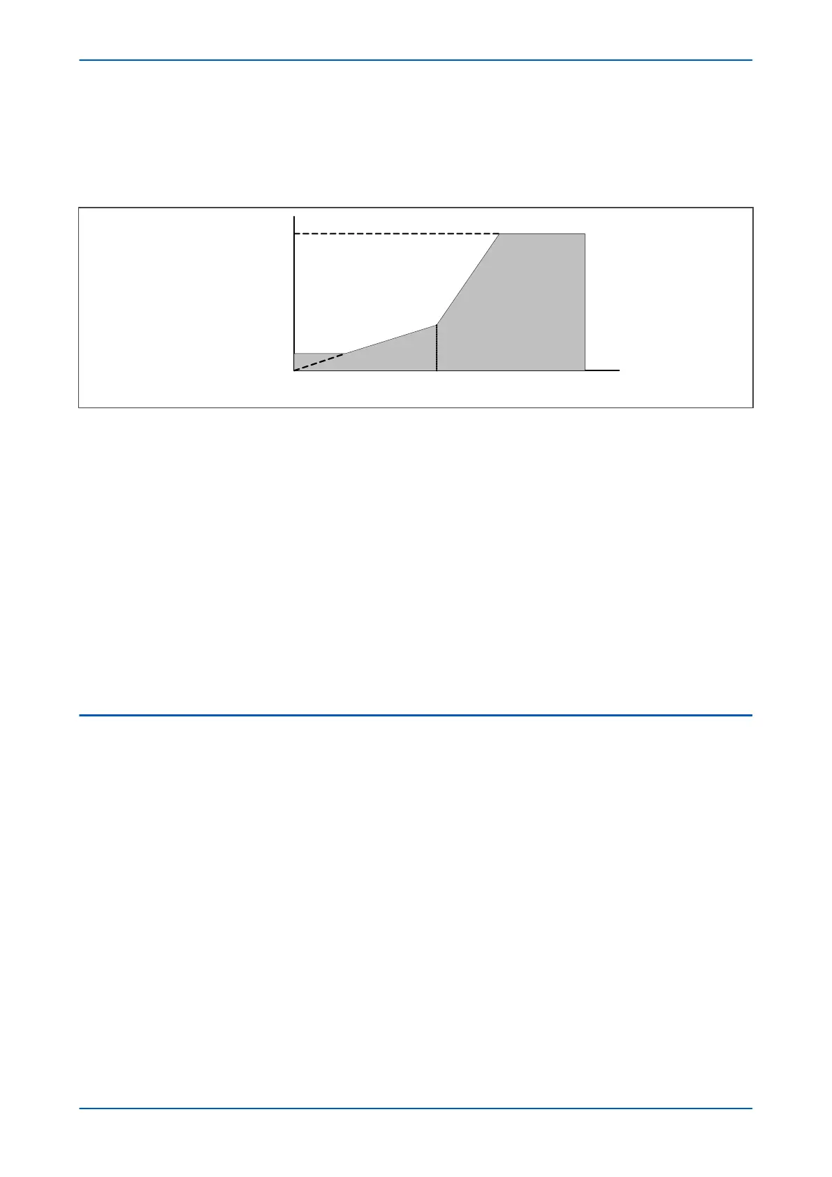
This is achieved by defining an operating current characteristic. Often a triple slope characteristic is used as shown
below.
K1
K2
Restraint region
Operate region
Is2
I
s1
Ibias
Idiff
V00664
High Set Threshold
Figure 35: Compensation using biased differential characteristic
Idiff is the differ
ential current, which is the vector sum of all the current inputs. Ibias is a current which is
proportional to the scalar sum of all currents entering and leaving the zone. The bias current is used to calculate
an operating current. If the differential current calculated by the IED is above the operation current, then the
device will trip (providing no blocking signals are asserted).
The characteristic can be defined by setting certain parameters such as the minimum operating current Is1 (Iset
1), Is2 (Iset 2), K1 and K2. Is1 sets the minimum operating current. Is2 sets the level of bias current at which the
steeper slope sets in. Constants K1 and K2 define the slopes. A High Set Threshold is usually defined, which ensures
the device will operate for very high currents, even if blocking signals are present.
The slope parts of the characteristic curve provide stability for external faults that cause CT saturation. The high
bias current region of the characteristic curve has a steeper slope than the low bias current region in order to
improve the stability even further for high-current external faults. The first slope, K1, compensates for CT errors
and tap changer errors. The second slope, K2, compensates for CT saturation. Is1 should be set above transient
overfluxing and Is2 should be considered as the transformer full load current. The CTs are sized according to the
transformer full load current.
2.3 THREE-PHASE TRANSFORMER CONNECTION TYPES
There are two ways of connecting a three-phase transformer winding:
● S
tar-connected (sometimes known as Y, or Wye)
●
Delta-connected (sometimes known as D or D)
In some transformers, the windings are split at the centre point and terminals are brought out so that they can
also be interconnected. These windings can be zig-zag connected (Z-connected).
The more common connection types are:
● Y-y
● Y-d
● Y-z
● D-d
● D-y
● D-z
To differentiate between the low and high voltage sides of the transformer, a standard convention has been
adopted whereby lower case is used for the low voltage side and upper case is used for the high voltage side.
P64x Chapter 6 - Transformer Differential Protection
P64x-TM-EN-1.3 101
 Loading...


