EasyManuals Logo

GE P642 User Manual

GE P642
592 pages
To Next Page IconTo Next Page
To Previous Page IconTo Previous Page
Page #428 background imageLoading...
Page #428 background image
5 CASE DIMENSIONS
Not all products are available in all case sizes.
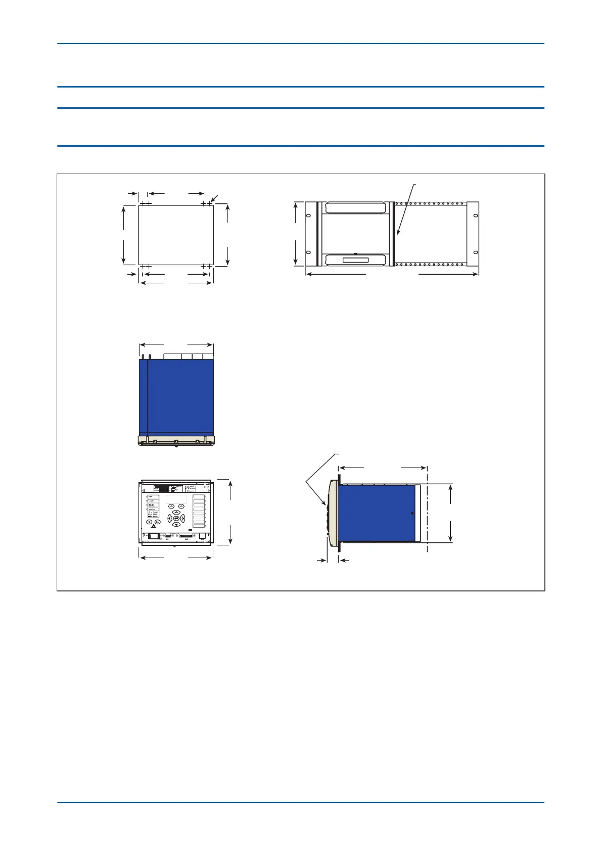
5.1 CASE DIMENSIONS 40TE
E01411
Front view
A = Clearance holes
B = Mouting holes
Flush mouting panel
Panel cut-out details
Note: If mouting plate is required
use flush mounting cut out
dimentions
8 off holes Dia. 3.4
Sealing
strip
483 (19” rack)
All dimensons in mm
Secondary cover (when fitted)
Incl. wiring
Side view
max.
206.00
30.00
240.00
157.5
177.00
200.00
177.0
(4U)
202.00
181.30
10.35
159.00
23.30
155.40
168.00
A B
B A
B A
A B
Figure 166: 40TE case dimensions
Chapter 18 - Installation P64x
404 P64x-TM-EN-1.3

Table of Contents

Questions and Answers:

Question and Answer IconNeed help?

Do you have a question about the GE P642 and is the answer not in the manual?

GE P642 Specifications

General IconGeneral
BrandGE
ModelP642
CategoryRelays
LanguageEnglish

Related product manuals