If the CT para mismat
ch alarm is asserted the protection is also blocked.
The phase current measured values of the windings of the protected object are always scaled by the relevant
matching factors. These are then available for further processing. Consequently, all threshold values and
measured values refer back to the relevant reference currents rather than to the transformer nominal currents or
the nominal currents of the device.
3.6 SETTING UP ZERO SEQUENCE FILTERING
There are two modes of operation for zero sequence filtering; simple and advanced. You set the operation mode
with the Set Mode setting in the DIFFPR
OTECTION column.
In simple mode, you cannot disable zero sequence filtering. It is automatically implemented for all earthed
windings. You can define whether a winding is earthed or not with the settings HV Grounding, LV Grounding and
TV Grounding in the SYSTEM CONFIG column. If a setting is set to grounded, zero sequence filtering will always
be implemented for that winding. If set to Ungrounded, it will not be implemented.
In advanced mode, you can enable or disable zero sequence filtering manually using the settings Zero seq filt HV,
Zero seq filt LV and Zero seq filt TV in the DIFF PROTECTION column.
3.7 TRIPPING CHARACTERISTICS
The differential and bias currents for each phase are calculated from the current variables after amplitude and
v
ector group matching.
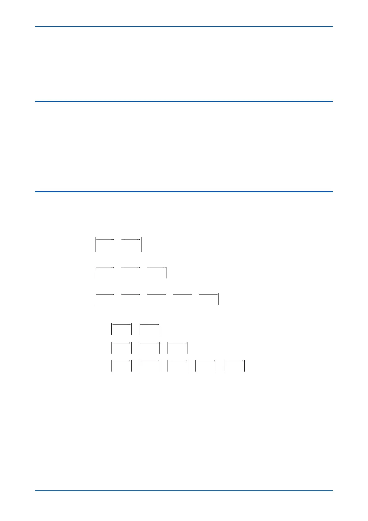
The differential current is the vector sum of the CT current inputs as follows:
P I I I
P
I
diff y s y CT s y CT
d
642
643
1 2
:
:
, , , , ,
= +
iiff y s y CT s y CT s y CT
I I I
P
, , , , , , ,
= + +
1 2 3
645::
,
, , , , , ,
I I I I
diff y s y CT s y CT s y CT
= + + +
1 2 3
II I
s
y CT s y CT, , , ,4 5
+
The bias current is defined as half of the scalar sum of the CT current inputs:
P I I I
P
I
bias y s y CT s y CT
642 0 5
643
1 2
: .
:
, , , , ,
= ⋅ +
bbias y s y CT s y CT s y CT
I
I I
, , , , , , ,
.= ⋅ + +0 5
1 2 3
=
⋅ + +P I I I I
bias y s y CT s y CT s
645 0 5
1 2
: .
, , , , , ,
yy CT s y CT s y CT
I
I
, , , , ,3 4 5
+ +
where:
● y is the measur
ed phase (A, B or C)
● I
s
is the current after the amplitude and vector group are matched.
The tripping characteristic has two knees. The first knee is dependent on the settings of Is1 and K1. The second
knee is defined by the setting Is2. The lower slope provides stability for low external faults. The higher slope
provides stability for high through fault conditions, since transient differential currents may be present due to
current transformer saturation.
Chapter 6 - Transformer Differential Protection P64x
110 P64x-TM-EN-1.3

 Loading...


