2 THERMAL OVERLOAD PROTECTION
Transformer overheating can be caused due to failures of the cooling system, external faults that are not cleared
pr
omptly, or overload and abnormal system conditions. These abnormal conditions include low frequency, high
voltage, non-sinusoidal load current, or phase-voltage imbalance.
Overheating shortens the life of the transformer insulation in proportion to the duration and magnitude of the high
temperature. If excessive, this may even result in an immediate insulation failure. Overheating can also generate
gases that could result in electrical failure, or cause the transformer coolant to be heated above its flashpoint
temperature, introducing the risk of fire.
Studies suggest that the life of insulation is approximately halved for each 10°C rise in temperature above the
rated value. However, the life of insulation is not wholly dependent on the rise in temperature but on the time the
insulation is subjected to this elevated temperature. Due to the relatively large heat storage capacity of a
transformer, infrequent overloads of short duration may not damage it. However, sustained overloads of a few
percent may result in premature aging and consequent insulation failure.
Transformer thermal overload protection is designed to protect equipment from sustained overload. Thermal
overload protection allows modest but transient overload conditions to occur, while tripping for sustained
overloads, which would not be detected by standard overcurrent protection.
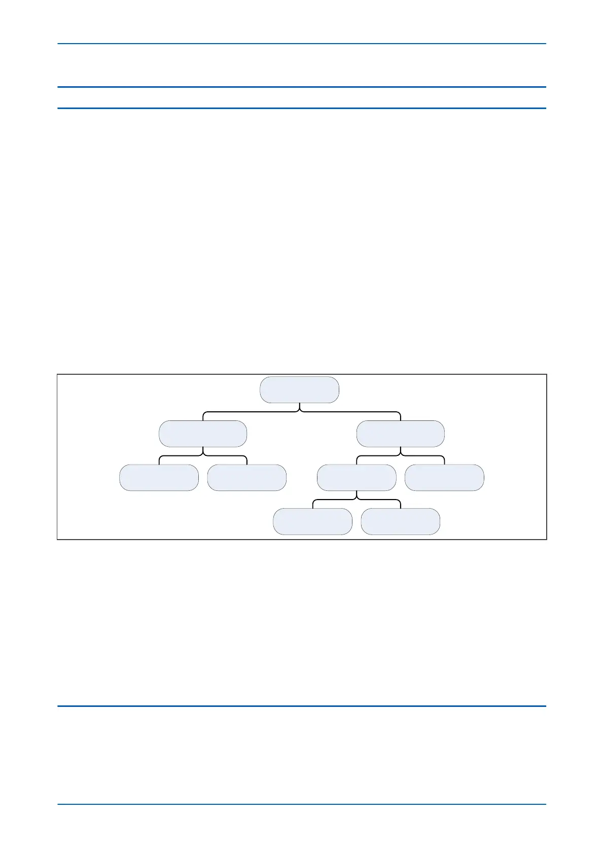
Transformer Losses
The losses in a transformer are shown in the following diagram:
V03200
Transformer Losses
Load Losses No Load Losses
Copper Losses
Eddy-current Losses Hysteresis Losses
Stray Losses Apparent Losses
Core Losses
(Iron Losses)
Figure 62: Transformer losses
The flow of the magnetising curr
ent through the resistance of the winding creates a real but generally relatively
small I
2
R loss and voltage drop. The loss that is due to this magnetizing current in the primary winding is called the
apparent loss.
Time-varying fluxes in iron-based materials, cause losses called core losses, or iron losses. These iron losses are
divided into two categories; hysteresis losses and eddy-current losses.
The sum of copper losses and the stray losses is called the load loss. Copper losses are due to the flow of load
currents through the primary and secondary windings. They are equal to I
2
R, and they heat up the wires and
cause voltage drops. Stray losses are due to the stray capacitance and leakage inductance. Stray capacitance
exists between turns, between one winding and another, and between windings and the core.
2.1 THERMAL OVERLOAD IMPLEMENTATION
The thermal overload protection in this device is based on the IEEE Standard C57.91-1995. It provides thermal
overload protection for either an individual winding or the transformer as a whole. The thermal overload
protection settings are in the THERMAL OVERLOAD column.
Chapter 7 - Transformer Condition Monitoring P64x
144 P64x-TM-EN-1.3
 Loading...


