A2
B2
C
2
A1
B
1
C1
a2
b
2
c2
yn
a
1
b1
c1
A2
B2
C
2
A1
B
1
C1
YN
b2
a
2
c2
b2
a
2
c2
a
b
c
A2
B2
C2
A1
B
1
C1
a2
b
2
c2
a1
b
1
c1
YN yn
A2
B2
C
2
A1
B
1
C1
a2
b
2
c2
a1
b
1
c1
b1 c1
a
1
a1
b
1 c1
b
a c
Yy6
Dy11
A2
C
2 B2
A
A
2
B2C2
B
C
B
A
2
B2C2
A
C
HV winding LV winding Winding Connection Phase ShiftType
1
80°
Dd6 1
80°
30°
Yd11
A2
C
2 B2
30°
Dz6
Yz11 3
0°
C2
a4
b
4
c4
A2
C
2 B2
a3
b
3
c3
A2
B2
C2
n
c2c4 c1
b
4 b2 b1
a1a2a4
a4
b
4
c4
n
c3 c2
c1
b
3 b2
b1
a1
a2a3
A
A
2
B2
B
C
c3
b
3
a3
180°
A2
B2
C
2
A1
B
1
C1
YN
V03126
c2
b
2
a2
a1
b
1
c1
c
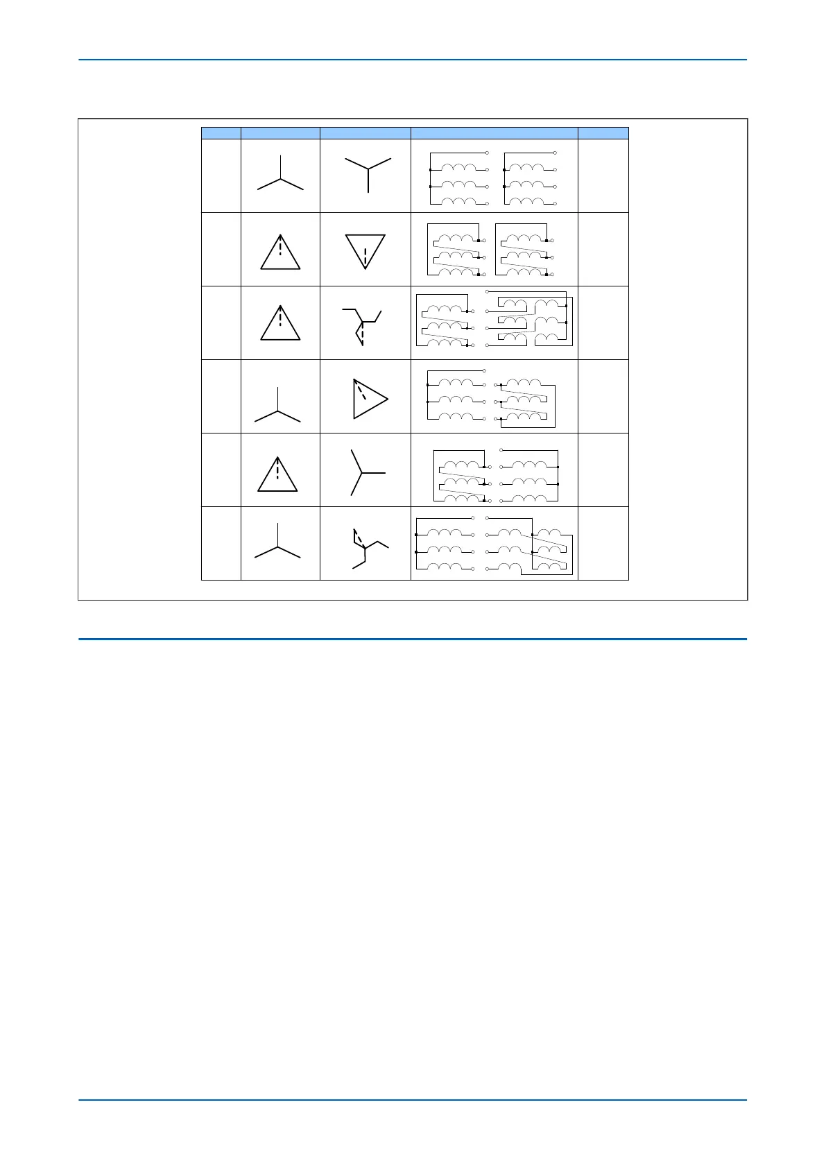
Figure 37: Transformer winding connections - part 2
2.4 PHASE AND AMPLITUDE COMPENSATION
A power transformer is designed to convert voltages. This means the line currents either side of the transformer
ar
e different in magnitude. If identical CTs were used on both sides of the transformer, the differential protection
circuit would be unbalanced, causing a differential current. Obviously, this has to be compensated for. Amplitude
compensation is theoretically arranged by having a suitable turns ratio on the secondary CT. Ideally, selecting CT
ratios that exactly match the inverse of the transformer turns ratio would compensate for the difference in the
transformer current magnitudes. However, the CT ratios associated with available CTs typically do not provide
exact ratio matching. Also for Y-delta or delta-Y connected transformers, the voltage and current magnitudes used
are changed by a factor of Ö3. Further, a phase shift is introduced, meaning the secondary side is out of phase with
the primary side. So further amplitude compensation, as well as phase compensation is required.
Before the advent of numerical IEDs, this compensation was achieved by choosing CTs with appropriate turns
ratios and connection types, and introducing interposing CTs with appropriate connection types. Of course, having
CTs with different turns ratios and connection types on each side of the protected zone exacerbates the CT errors,
therefore increasing the need for good through-fault compensation.
With modern IEDs, it is possible to do a great deal of the compensation in software, so simple Y-connected CTs can
be used on both sides of the transformer irrespective of the connection types. The CTs are chosen such that their
respective turns ratios provide a nominal current usable by the IED (1A or 5A). This in itself provides a certain
amount of amplitude compensation, but there will invariably be a CT ratio mismatch. This mismatch is
compensated for by software in the IED. The device calculates suitable values based on the reference power
rating, transformer voltage ratings, CT ratios and connection type (star or delta) to scale the secondary currents to
a common base.
Chapter 6 - Transformer Differential Protection P64x
104 P64x-TM-EN-1.3

 Loading...


