Ibias /Inom
I
diff/Inom
Is1
Is-HS1
I
s-HS2
Is2
K
1
K2
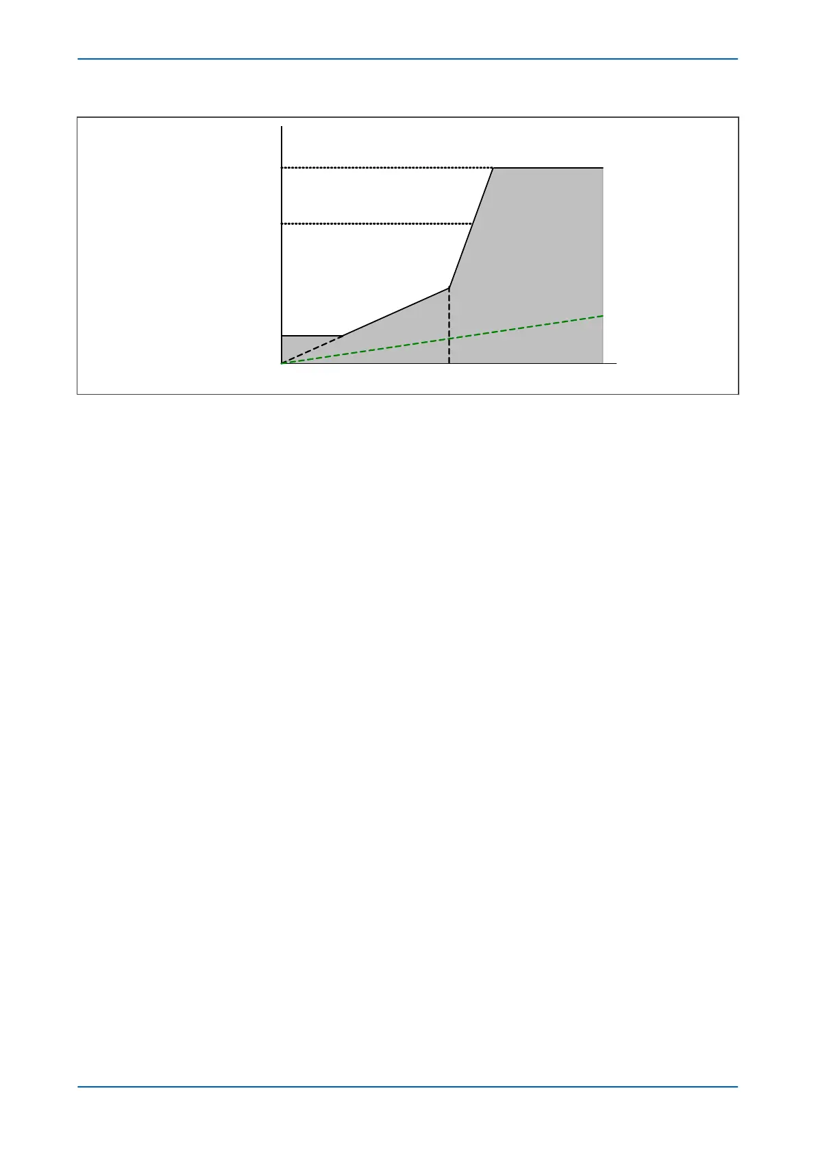
Restraint region
O
perate region
V03110
TC and CT errors
Figure 41: Transformer biased tripping characteristic
Once the differential and bias currents are calculated, the following comparisons are made and an operate/
restrain signal is obtained:
For the flat slope range: 0 ≤ I
bias max
≤ I
s1
/K
1
I
di
≥ I
s1
+ tr
ansient bias
For the K1 slope range: I
s1
/K
1
≤ I
bias max
≤ I
s2
I
di
≥ K1.I
bias max
+ tr
ansient bias
For the K2 slope range: I
s2
≤ I
bias max
≤ I
s-HS2
/K2
I
di
≥ K1.I
s2
+ K2(I
bias max
- I
s2
)
+
transient bias
3.7.1 HIGH-SET FUNCTION
The High Set 1 algorithm uses a peak detection method to achieve fast operating times. The peak value is the
lar
gest absolute value of differential current in the latest cycle. Since the High Set 1 algorithm uses a peak
detection method, Is-HS1 is set above the expected highest magnetizing inrush peak to maintain immunity to
magnetizing inrush conditions. For a High Set 1 trip, two conditions must be fulfilled:
● The peak value of the differential current is greater than Is-HS1 setting.
● The bias characteristic is in the operate region.
If the differential current is above the adjustable Is-HS1 threshold, the device will trip if in the Operate region, but
not in the restrain region. However, second harmonic blocking and overfluxing blocking are NOT taken into
account. The High Set 1 resets when the differential and bias currents are in the restraint area.
If the differential current is above the adjustable Is-HS2 threshold, bias current is not taken into account and the
device will trip regardless. As with High Set 1, second harmonic blocking and overfluxing blocking are NOT taken
into account. The High Set 2 element resets when the differential current drops below 0.95*Is-HS2.
3.7.2 CIRCUITRY FAIL ALARM
The circuitry fail alarm logic requires the following settings:
Cir
cuitry Fail: to enable or disable the function
Is-cctfail: to define the minimum differential threshold
K-cctfail: to define the slope gradient
P64x Chapter 6 - Transformer Differential Protection
P64x-TM-EN-1.3 111

 Loading...


