I
S
V
K
I
S
V
ref n
ref
nom n
amp n
nom n
ref
nom n
,
,
,
,
,
= =
3
3
where:
● Sr
ef = common reference power for all ends
● Iref,n = reference current for the respective CT input
● Kamp,n = amplitude-matching factor for the respective CT input
● Inom,n = primary nominal currents for the respective CT input
● Vnom,n = primary nominal voltage for the respective CT input
The device also checks that the matching factors are within their permissible ranges. The matching factors must
satisfy the condition:
0.05 <= Kamp <= 15 for standard CTs
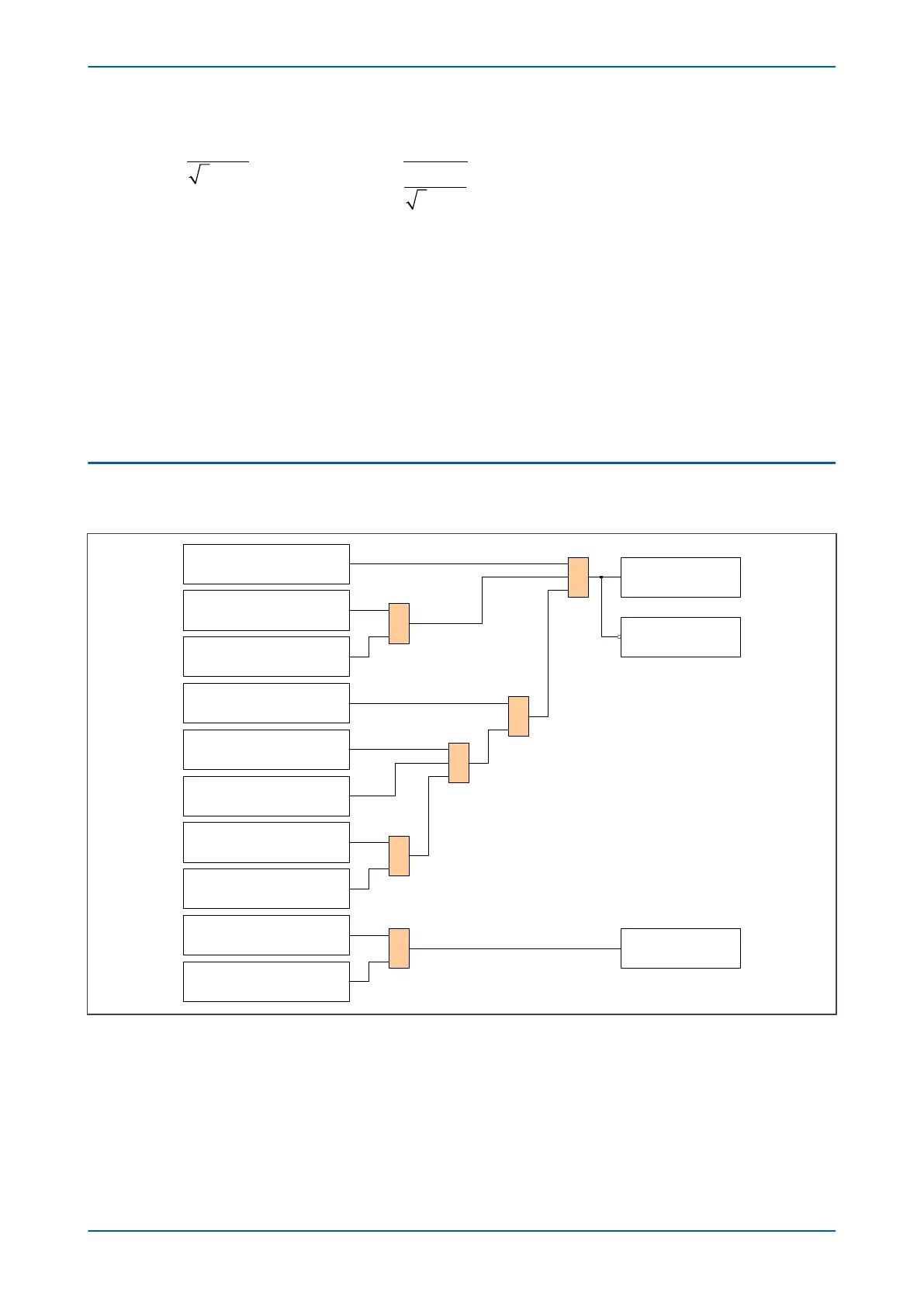
3.5 CT PARAMETER MISMATCH
The CT parameter (CT Para) mismatch logic implemented in firmware is as follows:
V03108
One CT is configured to more than one
winding simultaneously
1
Winding configuration = HV/LV
The ratio correction factor (amplitude
matching factor ) of any CT is out of range
Winding configuration = HV/LV/TV
The ratio correction factor (amplitude
matching factor ) of the CTs associated with
the HV winding is out of range
The ratio correction factor (amplitude
matching factor ) of the CTs associated with
the TV winding is out of range
The ratio correction factor (amplitude
matching factor ) of the CTs associated with
the LV winding is out of range
The ratio correction factor (amplitude
matching factor ) of the CTs associated with
the TV winding is greater than allowed
The ratio correction factor (amplitude
matching factor ) of the CTs associated with
the TV winding is less than 0.05
&
1
&
The ratio correction factor (amplitude
matching factor ) of the CTs associated with
the TV winding is out of range
&
&
Set CT para mismatch alarm
Reset CT para mismatch alarm
Remove the current inputs from
the differential calculation
Figure 40: CT parameter mismatch logic diagram
If any of the ratio corr
ection factors in two-winding applications are out of range, the CT para mismatch alarm is
asserted. In multi-winding applications, the alarm is asserted if the ratio correction factor of the CTs associated
with HV or LV windings are out of range or the ratio correction factor of the CTs associated to TV winding is greater
than 15 for standard CTs.
If the ratio correction factor of the CT associated to TV winding is lower than 0.05, this current is removed from the
differential calculation, as shown in the logic diagram.
P64x Chapter 6 - Transformer Differential Protection
P64x-TM-EN-1.3 109

 Loading...


