2.1 RESISTANCE-EARTHED STAR WINDINGS
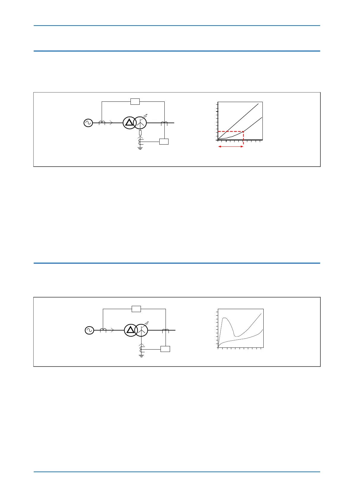
Most distribution systems use resistance-earthed systems to limit the fault current. Consider the diagram below,
which depicts an ear
th fault on the star winding of a resistance-earthed Dyn transformer (Dyn = Delta-Star with
star-point neutral connection).
V00669
Source
Current p.u.
(x full load)
Fault position from neutral
(Impedance earthing)
20% 100%
Winding not protected
Pickup
1.0
87
64
I
S
I
F
I
F
I
S
0.2
I
F
Figure 72: REF Protection for resistance-earthed systems
The v
alue of fault current (I
F
) depends on two factors:
● The value of earthing resistance (which makes the fault path impedance negligible)
● The fault point voltage (which is governed by the fault location).
Because the fault current (I
F
) is governed by the resistance, its value is directly proportional to the location of the
fault.
A restricted earth fault element is connected to measure I
F
directly. This provides very sensitive earth fault
protection. The overall differential protection is less sensitive, since it only measures the HV current I
S
. The value of
I
S
is limited by the number of faulty secondary turns in relation to the HV turns.
2.2 SOLIDLY-EARTHED STAR WINDINGS
Most transmission systems use solidly-earthed systems. Consider the diagram below, which depicts an earth fault
on the star winding of a solidly-ear
thed Dyn transformer.
V00670
Current p.u.
(x full load)
Source
Fault position from neutral
(Solid earthing)
20% 40% 60% 80% 100%
87
I
S
I
F
I
F
64
I
F
I
S
10
8
6
4
2
Figure 73: REF Protection for solidly earthed system
In this case, the fault curr
ent I
F
is dependent on:
● The leakage reactance of the winding
● The impedance in the fault path
● The fault point voltage (which is governed by the fault location)
In this case, the value of fault current (I
F
) varies with the fault location in a complex manner.
A restricted earth fault element is connected to measure I
F
directly. This provides very sensitive earth fault
protection.
P64x Chapter 8 - Restricted Earth Fault Protection
P64x-TM-EN-1.3 169

 Loading...


