5 RTD PROTECTION
Prolonged overloading of transformers may cause their windings to overheat, resulting in premature aging of the
insulation, or in extr
eme cases, insulation failure. To protect against this, resistive temperature sensing devices
(RTDs) can be used to measure temperatures at various locations within a transformer. RTDs work by using the
resistance versus temperature characteristic of metals. When metal heats up, its resistance changes. This can be
used to feed back temperature information, which can be used by protection devices for temperature monitoring,
alarming, or making protection decisions.
Probes are usually placed in areas of the equipment that are susceptible to overheating or heat damage. This
could protect against winding Hotspot overheating or overtemperature in the insulating oil.
Direct temperature measurement can provide more reliable thermal protection than thermal model calculations.
Note:
Do Not select RTD options if RTD board is not fitted.
5.1 RTD PROTECTION IMPLEMENTATION
The P64x uses PT100 RTD probes to protect against any general or localized overheating. These can measure
temperatur
es between –40° and +300°C. At 0°C they have a resistance of 100 Ohms.
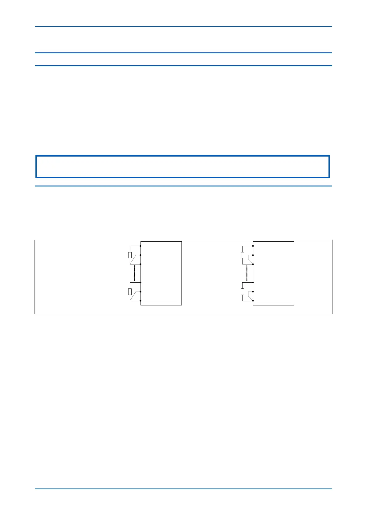
The device accepts inputs from up to ten 2-wire or 3-wire PT100 resistive temperature sensing devices (RTD). These
are connected as shown:
V03202
IED
RTD 1
RTD 10
3-wire PT100 RTDs
IED
2-wire PT100 RTDs
RTD 1
RTD 10
Figure 65: Connection for RTD thermal probes
You can enable or disable each RTD using the Select RTD setting in the RTD PROTECTION column of the relevant
settings group. The setting contains a binary string of ten digits to represent the 10 RTDs in sequence from right to
left. For example if you set Select RTD to 0000000111, RTD1, RTD2 and RTD3 would be enabled and the associated
settings would be visible in the menu.
You set the temperature setting for the alarm stage for each RTD in the RTD Alarm Set cells and the alarm stage
time delay in the RTD Alarm Dly cells.
Likewise, you set the trip stage for each RTD in the RTD Trip Set cells and the trip stage time delay in the RTD Trip
Dly cells.
Should the measured resistance of an RTD be outside of the permitted range, an RTD failure alarm is raised,
indicating an open or short circuit RTD input. These conditions are signalled by the DDB signals RTD Open Cct, RTD
Short Cct and RTD Data Error. These DDB statuses are also shown in the MEASUREMENTS 3 column.
DDB signals are also available to indicate the alarm and trip of the each and any RTD. You can set the monitor bit
cells in the COMMISSION TESTS column to view the statuses of these signals.
P64x Chapter 7 - Transformer Condition Monitoring
P64x-TM-EN-1.3 157
 Loading...


