3 CURRENT TRANSFORMER SUPERVISION
The Current Transformer Supervision function (CTS) is used to detect failure of the AC current inputs to the
pr
otection. This may be caused by internal current transformer faults, overloading, or faults on the wiring. If there
is a failure of the AC current input, the protection could misinterpret this as a failure of the actual phase currents
on the power system, which could result in maloperation. Also, interruption in the AC current circuits can cause
dangerous CT secondary voltages to be generated.
3.1 CTS IMPLEMENTATION
Differential current transformer supervision is based on the measurement of the ratio of negative sequence
curr
ent to positive sequence current (I2/I1) for each CT. When this ratio is not zero, one of the following two
conditions may be present:
● There is an unbalanced fault
● There is a 1 or 2 phase CT problem
If the I2/I1 ratio is greater than the high set value, CTS I2/I1>2 at all ends, it is almost certainly a genuine fault
condition, thus the CTS will not operate. If this ratio is detected at one end only, one of the following conditions
may be present:
● A CT problem
● A single end fed fault condition
The positive sequence current I1 is used to confirm whether it is a CT problem or not. If I1 is greater than the
setting CTS I1 at all terminals, it must be a CT problem and CTS is allowed to operate. If this condition is detected at
only one end, the device assumes it is caused by either an inrush condition or a single-end fed internal fault. In this
case, CTS operation is blocked.
The CTS status setting under the CT SUPERVISION sub-heading can be set to either indication or
restraint. In indication mode, the CTS alarm time delay is automatically set to zero. If a CT failure is present, an
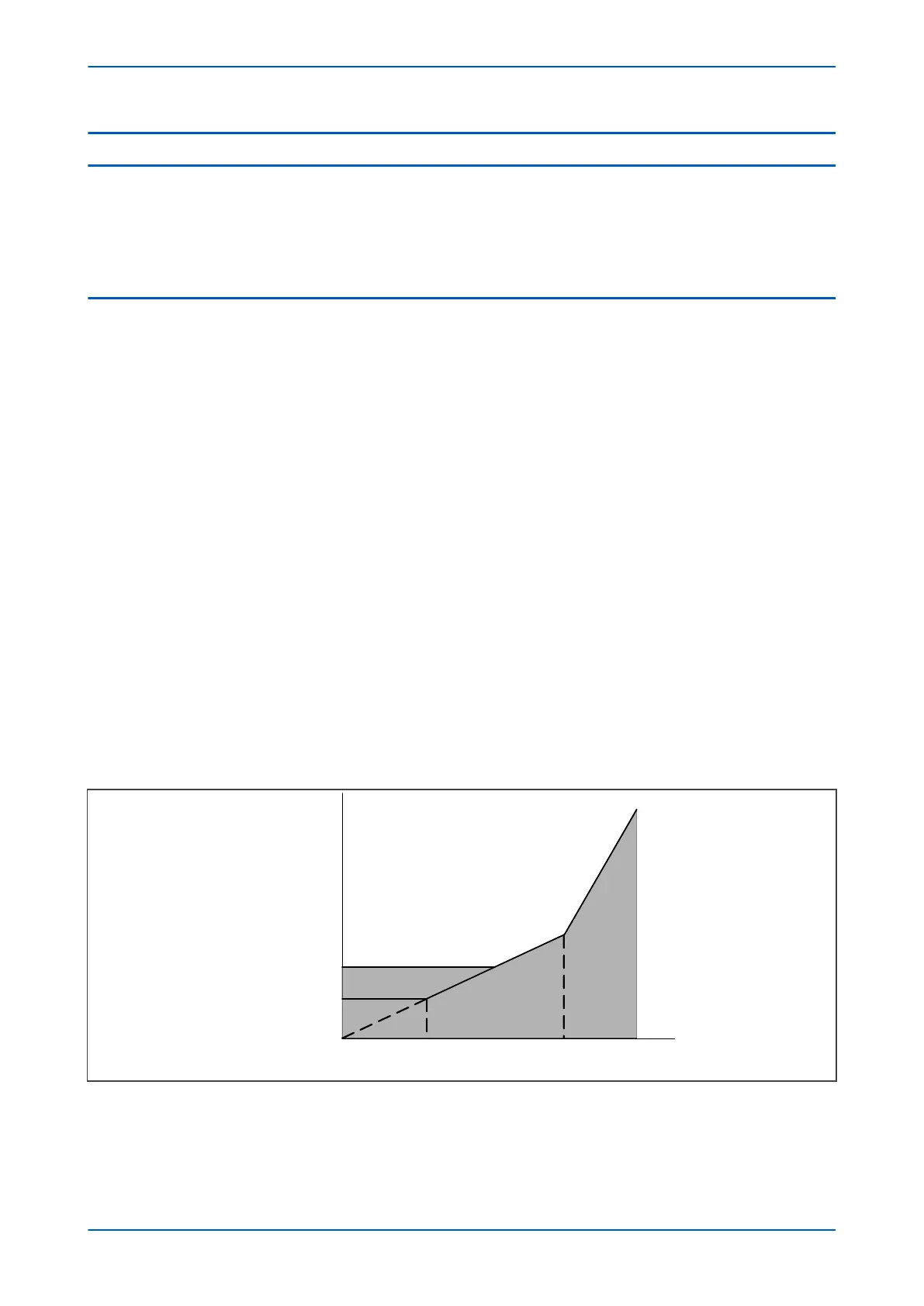
alarm would be issued without delay, but the differential protection would remain unrestricted. In restraint mode,
the differential protection is blocked for 20 ms after CT failure has been detected, after which the restraint region
of the bias characteristic increases according to the setting Is-CTS , which has been defined in the DIFF
PROTECTION column.
K2
K1
Is1/K1 Is2 Ibias/In
Is1
Is-CTS
Idiff/In
Restraint region
Operating region
V01226
Figure 133: CTS restraint region increase
The low impedance REF
, earth fault and NPS overcurrent protection functions are internally blocked by CTS when a
CT failure is detected in the relevant CT. However, earth fault protection is immune to CTS blocking if IN> input is
set to measured.
P64x Chapter 14 - Supervision
P64x-TM-EN-1.3 291
 Loading...


