5.9.1.3 STUB BUS TRIPPING
You can protect the Stub Bus zone by a non-directional DT phase overcurrent element with a delay time set to zero
second. T
o issue a Stub Bus trip, the overcurrent element and the relevant Stub Bus active DDB signals must both
be high. You can configure the Stub Bus tripping scheme in PSL.
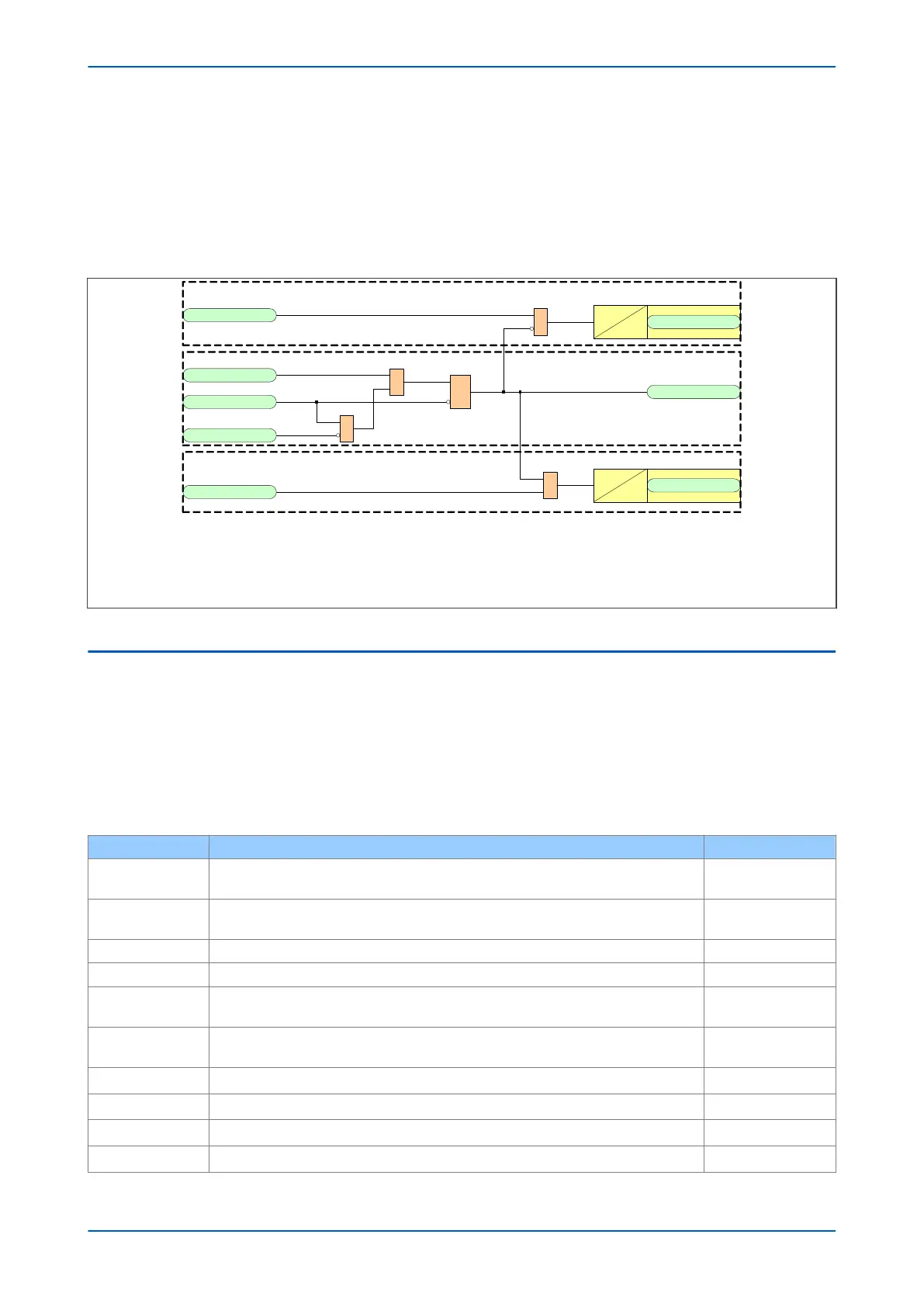
5.9.2 STUB BUS SCHEME
V03129
Idiff Trip
S
R
Q
89b
&
& Output R4
Dwell
0
100
HV StubBus Act
&
HV UndCurrent
Input L2
89a
Input L1
& Output R1
Dwell
0
100
HV StubBus Trip
Idiff Trip
POC 1 I>3 Trip
This example applies to the HV element only . The LV and TV elements follow the same principles .
In this example, the following applies :
· The differential trip output is connected to output relay 4
· The HV Stub bus trip output is connected to output relay 1
· The HV stage 3 phase overcurrent element is used
· The 89a contact is connected to opto -input 1
· The 89b contact is connected to opto -input 2
Blocking
Activation
Tripping
Figure 61: Stub Bus Scheme Logic
5.10 TRANSFORMER DIFFERENTIAL PROTECTION CT REQUIREMENTS
The CT requirements detailed below are applicable to standard CTs.
5.10.1 CT REQUIREMENTS - TRANSFORMER APPLICATION
We strongly recommend Class X or Class 5P current transformers for transformer differential protection
applications.
The curr
ent transformer knee-point voltage requirements are based on the following settings:
Parameter Description Value
Is1
This sets the minimum differential current threshold required for the transformer differential
pr
otection to trip.
0.2 pu
Is2
This defines the bias current threshold at which the second slope of the bias current
characteristic becomes active.
1 pu
K1 This setting defines the gradient of the first slope in the bias current characteristic. 30%
K2 This setting defines the gradient of the second slope in the bias current characteristic. 80%
Is-HS1
This setting defines the first High set threshold on the bias current characteristic. This setting
is only used in advanced mode.
10 pu
Is-HS2
This setting defines the second High set threshold on the bias current characteristic. This
setting is only used in advanced mode.
32 pu
Transient Bias This setting enables or disables the transient bias factor Enabled
Zero seq filt HV This setting enables or disables zero sequence filtering on the HV winding Enabled
Zero seq filt LV This setting enables or disables zero sequence filtering on the LV winding Enabled
Zero seq filt TV This setting enables or disables zero sequence filtering on the TV winding Enabled
Chapter 6 - Transformer Differential Protection P64x
138 P64x-TM-EN-1.3
 Loading...


