E03204
T
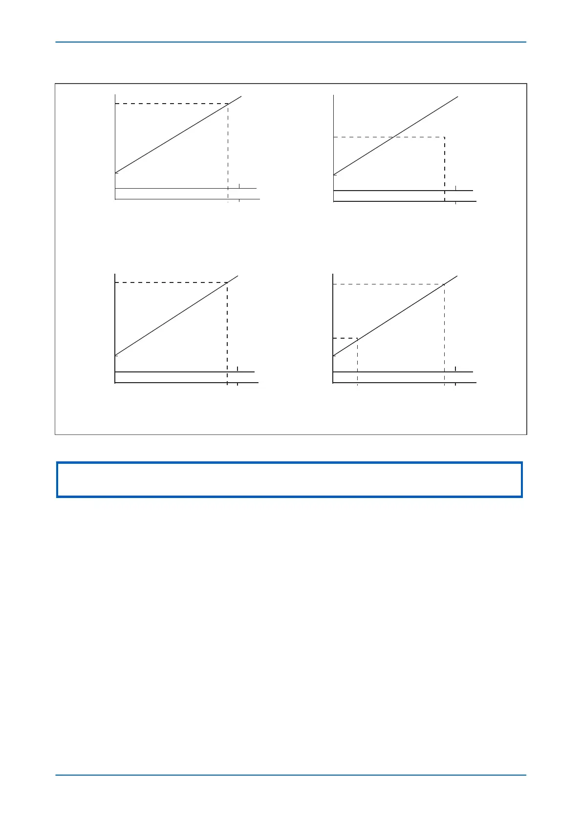
ransducer Value
Maximum
Minimum
Minimum
Maximum
Transducer Value
0 mA
0 mA
0 - 20 mA
20 mACurrent I/P
22.7556 mA
ADC
Count
4095
0 - 1 mA
1 mA
ADC
Count
4095
Current I/P
1.0836 mA
Maximum
Maximum
Minimum
Minimum
Transducer Value
Transducer Value
0 - 10 mA
ADC
Count
4095
ADC
Count
4095
0 mA
0 mA 4 mA
4 - 20 mA
10 mA
20 mA
Current I/P
22.7556 mA
Current I/P
22.7556 mA
0
0
0
0
Figure 67: Current loop input ranges
Not
e:
If the Maximum is set less than the Minimum, the slopes of the graphs will be negative.
Power-on diagnostics and continuous self-checking of the current loop inputs are integrated into the hardware.
When a failur
e is detected, the protection associated with all the current loop inputs is disabled and a single alarm
DDB signal (CL Card I/P Fail) is set and an alarm is raised. A maintenance record with an error code is also
recorded with additional details about the type of failure.
For the 4 – 20 mA input range, a current level below 4 mA indicates that there is a fault with the transducer or the
wiring. An instantaneous undercurrent alarm element is available, with a setting range from 0 to 4 mA. This
element controls a DDB output signal for each CL input (CL(n)I< Fail Alm), where (n) is the number of the CL input.
You can then map this to a user defined alarm if required.
Hysteresis is implemented for each protection element. For ‘Over’ protection, the drop-off/pick-up ratio is 95%, for
‘Under’ protection, the ratio is 105%.
A timer block input is available for each current loop input stage. This will reset the CL input timers of the relevant
stage if energized. If a current loop input is blocked, the protection and alarm timer stages and the 4 – 20 mA
undercurrent alarm associated with that input are blocked. The blocking signals may be useful for blocking the
current loop inputs when the CB is open for example.
DDB signals are available for each current loop input to indicate the start of alarm and trip stages. These are CLI(n)
Alarm Start, and CLI(n) Trip Start, CLI(n) Alarm and CLI(n) Trip, where (n) is the number of the current loop input.
The Monitor Bit cells of the COMMISSIONTESTS column can be configured to show the state of the DDB signals.
Chapter 7 - Transformer Condition Monitoring P64x
160 P64x-TM-EN-1.3

 Loading...


