E1 Series Servo Drive Thunder Software Operation Manual Servo Drive Configuration
HIWIN MIKROSYSTEM CORP. 4-75
4.5.3 Configuration of digital output signals
Each pin of CN6 has the default I/O signal configuration as the servo drive leaves the factory. Users can
modify its configuration and signal type. Follow the procedure below to modify configuration of digital output
signals.
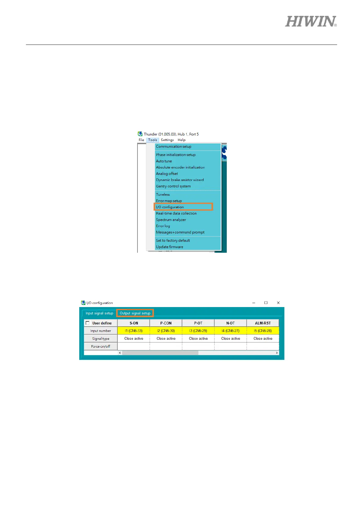
1. Select Tools in the menu bar, and click I/O configuration to open “I/O configuration” window.
Figure 4.5.3.1
2. Select Output signal setup tab.
Figure 4.5.3.2
3. Set digital output signal’s signal type: double-click Signal type column or click the pin in the diagram.
The descriptions are given in the following table. If it is set as “Close active”, the pin color is blue; if it
is set as “Open active”, the pin color is orange.

 Loading...


