Removal and Replacement Procedures
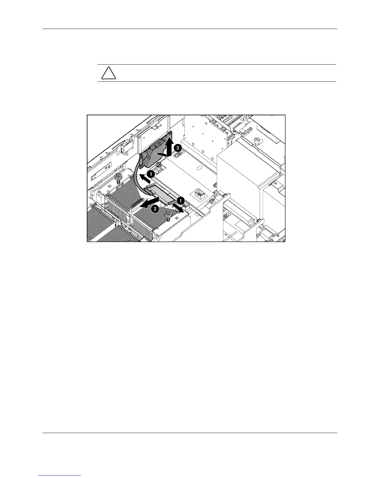
11. Using your fingernail, release the latch that connects each side of the 5i Plus Memory
Module to the system board until the module rises away from the system board (1).
CAUTION: Do not disconnect the cable connecting the BBWCE and the 5i Plus Memory
Module.
12. Disengage the BBWCE from the standoffs on the side of the chassis. Remove the
complete assembly from the server by pushing it from under the printed circuit board at
the standoff (2).
Figure 2-47: Removing the BBWC enabler and 5i Plus Memory Module
Reverse steps 1 through 12 to replace the BBWC Enabler and 5i Plus Memory Module.
HP ProLiant DL580 Generation 2 Server Maintenance and Service Guide 2-61
 Loading...