Connectors, LEDs, and Switches
Memory Board
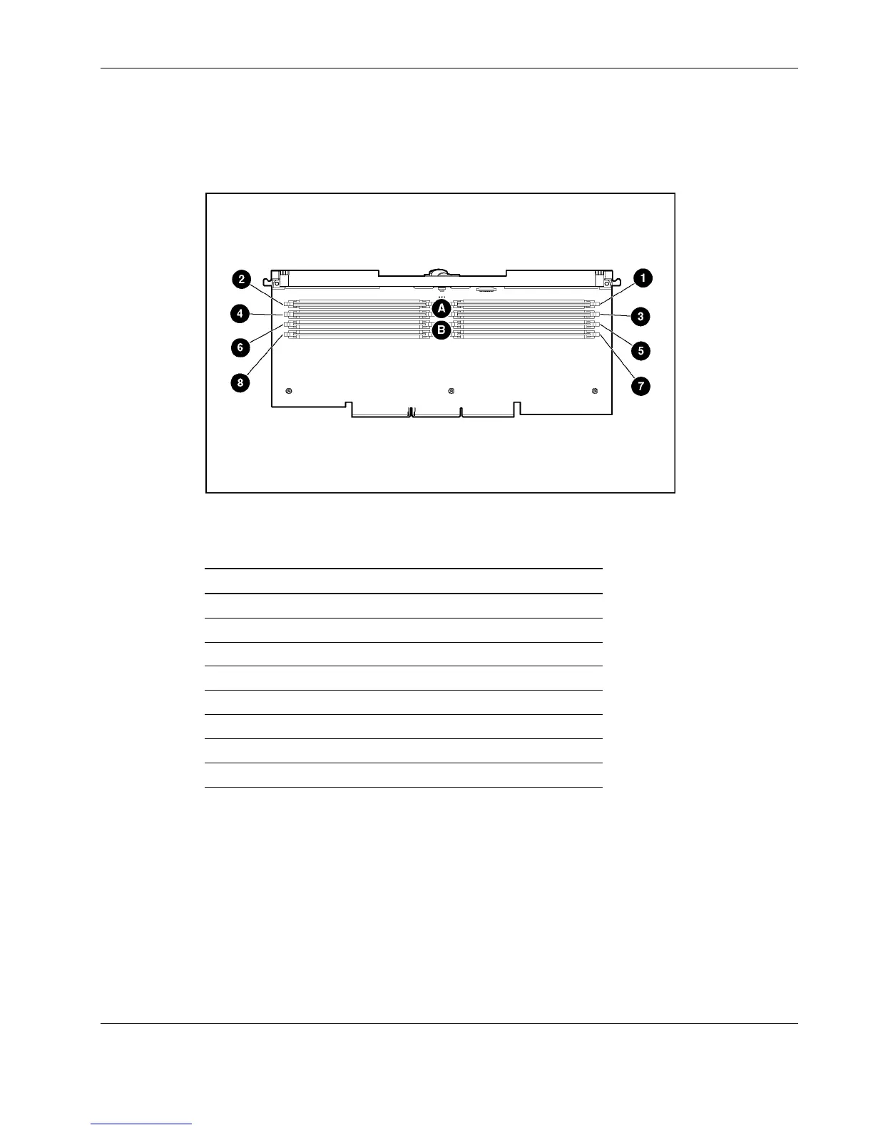
Figure 4-4 and Table 4-4 illustrate the connectors and DIMM banks located on the memory
board.
Figure 4-4: Memory board connectors and DIMM banks
Table 4-4: Memory Board Connectors and DIMM Banks
Item Description
1 DIMM slot 1, bank A (populated)
2 DIMM slot 2, bank A (populated)
3 DIMM slot 3, bank A (populated)
4 DIMM slot 4, bank A (populated)
5 DIMM slot 5, bank B
6 DIMM slot 6, bank B
7 DIMM slot 7, bank B
8 DIMM slot 8, bank B
HP ProLiant DL580 Generation 2 Server Maintenance and Service Guide 4-5
 Loading...