• During the idle state the input must be active. If not, a brake switch failure error will
be triggered.
• During the start of the run, the input must become inactive within the time period set
by LT01 + LT03 + 500mSec. If not, a brake switch failure error will be triggered.
• During the run, the brake switch input should be inactive. If during the run the input
becomes active, the run is allowed to be completed. In this case, upon switch off of
the STO inputs, a brake switch failure error will be triggered.
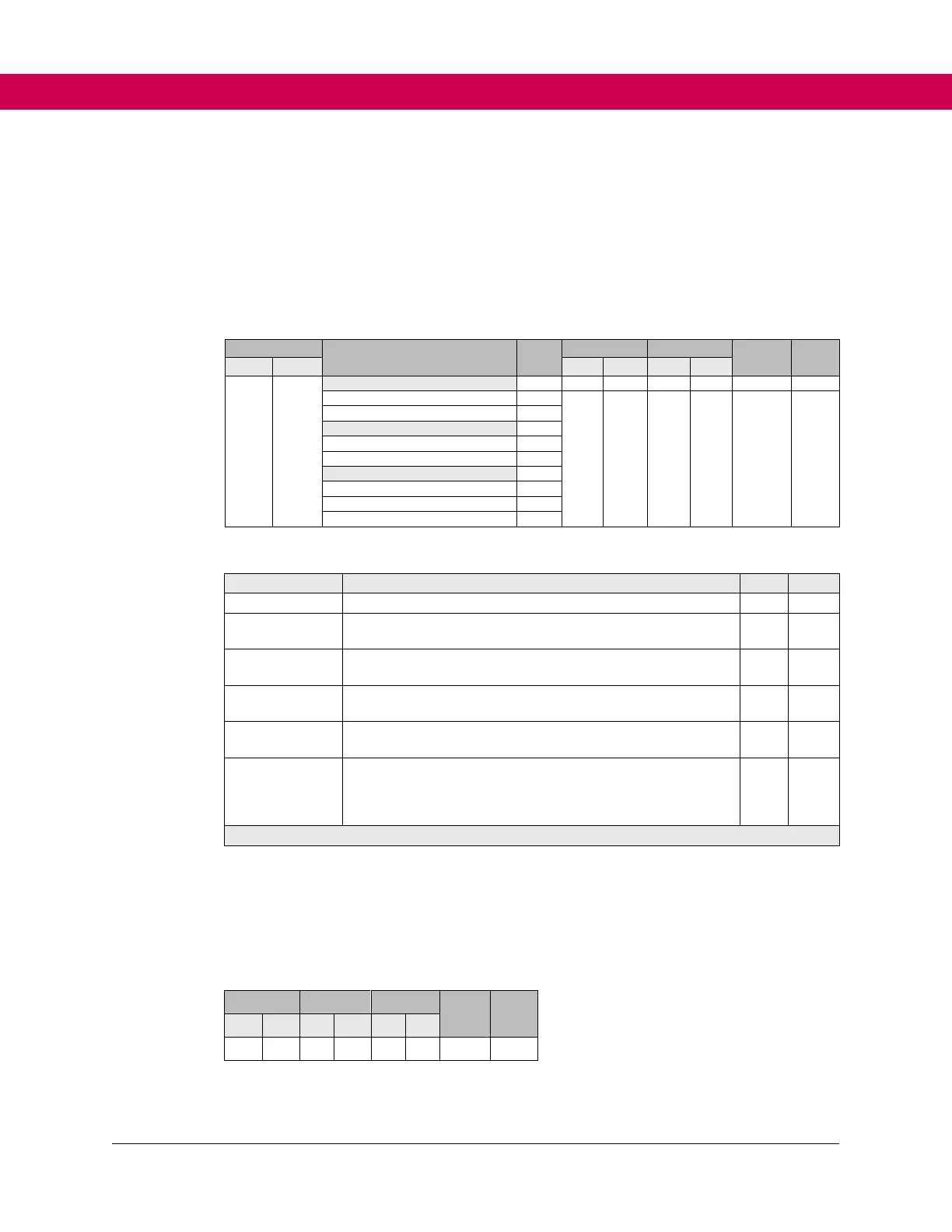
Table 14. LI20 Brake function settings
Neither brake switch inputs are active
Brake switch
Input 1 Active
The brake switch input X1C.5 is functionally active
Brake Switch
input 2 active
The brake switch input X1C.6 is functionally active
Brake switch faults will automatically reset up to the number
of times adjusted in LX01.
The brake switch fault will only reset 3 times, regardless of
the LX01 setting.
A manual reset of the fault on the drive is required. Even
after a power cycle, no auto reset is possible. Parameter
CH00 Forced Fault Reset will change to a value of 3. It must
be manually reset to a value of 0.
Default = General reset (0)
LI50 UPS Mode
This parameter is only active when an input (LI04-LI11) is set to use the UPS function.
The drive determines which direction will use less power based on brief torque
measurements made before the run and then commands the motor to run in the easy
direction.
• In default mode (0), with the UPS input active, both directions must be signaled to
activate the function.
 Loading...


