3.3.2 Assembly of the Wires
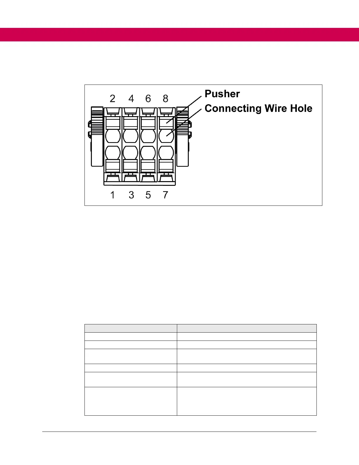
Figure 3. Assembly of the terminal X2B
Press pusher by hand. Insert connecting wires into the respective hole, so that no single
wires can be seen from the outside or bend outward. A first resistance must be overcome
when inserting. Release the pusher.
Check that the connecting wire is fixed and cannot be pulled out. It is important to ensure
that the connecting wire and not the insulation is clamped. The connecting wire can also
be inserted without pressing the pusher in case of cross-sections up to 1.00 mm².
3.3.3 Safety Status LED
Arrangement of the LEDs is defined in the respective manual of the F6.
The LED display of the safety mode indicates the following status:
Table 3. Status LED
No voltage supply of the safety module
Safety module in operation
Safety module in reset or new configuration will be
saved
Flashes for 30 seconds when a new user has
logged in.
Green Orange Double Flashing
Flashes orange briefly twice every 1.6 seconds.
Signals that the state of the bus communication is
not the data state. The safety module is in a safe
condition.
 Loading...


