EasyManuals Logo
Home>KEB>Inverter>F6

KEB F6 User Manual

KEB F6
305 pages
To Next Page IconTo Next Page
To Previous Page IconTo Previous Page
Page #229 background imageLoading...
Page #229 background image
Parameter Descriptions
© 2024 KEB America, Inc.
229
FB16 PDO4 Map Assignment
Hexadecimal address of diagnostics parameter mapped as Process Data Output 4.
 Refer to the Diagnostics Parameters (DG) section.
Motor Type
Setting Options
NUM
Range
Units
Default
Pass
Level
Ind.
PM
Min.
Max.
Imp.
Met.
RW
RW
See Parameter Description
-
0
73
-
-
4
Basic
8.15.5 Process Data Input Addresses
The function associated with PDI1, 2, 3, 4 must be assigned according to the information
contained in the controller telegram structure.
Parameter Structure (12345678):
Field Bus Parameter Hex Address (1 - 4) + Set (5 - 6) + Size, Bytes (7 - 8)
• The Field bus Parameter Hex Address is the drive parameter address of the PDI
function which data is mapped to.
Example: If FB17 PDI1 = 12810102, this would correspond to FB01 (1281h) =
Control Word; thus PDI1 = Control Word.
• Set: This can be fixed at 01
• Size: 16-bit = 02, 32-bit = 04
The defaults are established such that:
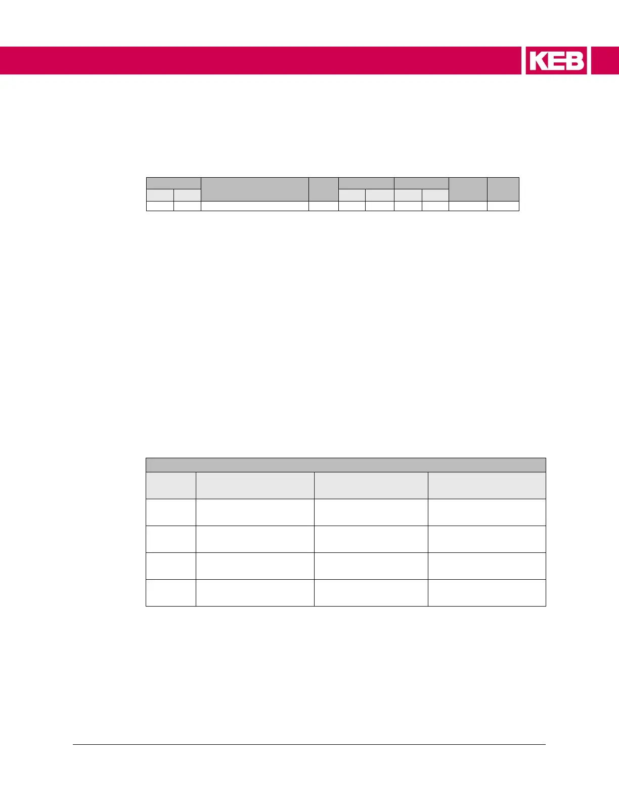
Table 37. Process data input defaults
US04 Control Type, DIN66019
PDI
Service 49 (4)
Service 50 (5)
Service 50
Serial Binary (6)
PDI1
(1281h)
FB01 Control Word
(1282h)
FB02 Speed
(1282h)
FB02 Speed
PDI2
(1282h)
FB02 Command Speed
(1281h)
FB01 Control Word
(1281h)
FB01 Control Word
PDI3
(1283h)
FB03 Pretorque
(1283h)
FB03 Pretorque
(1283h)
FB03 Pretorque
PDI4
(1284h)
FB04 Target Position
(1284h)
FB04 Target Position
(1284h)
FB04 Target Position

Table of Contents

Questions and Answers:

Question and Answer IconNeed help?

Do you have a question about the KEB F6 and is the answer not in the manual?

KEB F6 Specifications

General IconGeneral
BrandKEB
ModelF6
CategoryInverter
LanguageEnglish

Related product manuals