EasyManuals Logo
Home>KEB>Inverter>F6

KEB F6 User Manual

KEB F6
305 pages
To Next Page IconTo Next Page
To Previous Page IconTo Previous Page
Page #40 background imageLoading...
Page #40 background image
Control Connections
40
© 2024 KEB America, Inc.
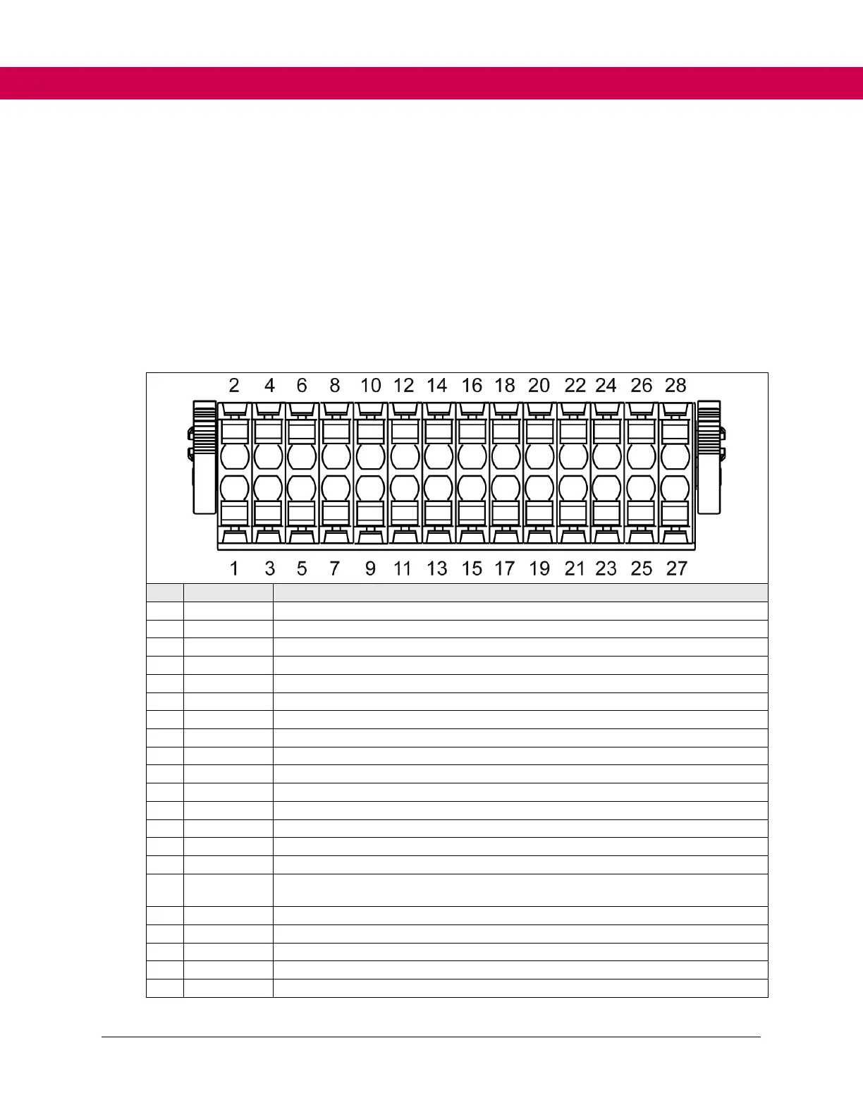
4.3 Control Terminal Strip X2A
The control terminal strip X2A is a 28-pole pluggable, double-row terminal strip with
spring-cage connection. It contains:
 8 digital inputs
 2 digital outputs
 1 Relay output
 2 analog inputs
 1 analog output
 CAN bus interface
 24V input and output
Pin
Name
Description
1
DI1 / AN3
Digital input 1
2
DI2
Digital input 2
3
DI3
Digital input 3
4
DI4
Digital input 4
5
DI5
Digital input 5
6
DI6
Digital input 6
7
DI7
Digital input 7
8
DI8
Digital input 8
9
0V
Reference potential for digital output
10
DO1
Digital output 1
11
0V
Reference potential for digital output
12
DO2
Digital output 2
13
RLB
Relay output / NC contact (no function at variant relay with positively driven contacts)
14
RLA
Relay output / NO contact
15
RLC
Relay output/ switching contact
16
24Vout
DC voltage output 24V (max. 100 mA together with terminal 26) for control the inputs
(SELV).
17
AN1-
non-isolated difference input 1
18
AN1+
Non-isolated difference input 1
19
AN2-
non-isolated difference input 2
20
AN2+
Non-isolated difference input 2
21
0V
Reference potential for analog inputs and outputs

Table of Contents

Questions and Answers:

Question and Answer IconNeed help?

Do you have a question about the KEB F6 and is the answer not in the manual?

KEB F6 Specifications

General IconGeneral
BrandKEB
ModelF6
CategoryInverter
LanguageEnglish

Related product manuals