Power Module Installation
1. Inspect the main frame guide rails. Remove any
debris which would interfere with power module
installation.
2. Clean the main frame rear support brackets. Apply
a light film of soap solution to each rubber bushing
(3, Figure 2-5) located at the rear of the subframe.
3. Check the subframe rollers making sure they roll
freely and are in the “roll–out” position. ( Figure
2-6).
4. Attach a lifting device to engine/alternator cradle
structure and front subframe lifting points (Figure
2-7).
The complete power module, including the hood
and grille weighs approximately 34,750 lbs. (15,760
kg). Make sure lifting device to be used has ade-
quate capacity.
5. Raise the power module and align the subframe
rollers within the main frame guide rails.
6. Lower the power module to the subframe guide
rails, relax the hoist slightly and roll the power
module into truck frame as far as possible before
the lifting chains contact the electrical cabinet.
7. Place stands or blocking under front of subframe
to support assembly while repositioning hoist.
8. Install a safety chain around the truck frame and
the subframe. The safety chain will prevent the
power unit from rolling forward.
9. Place a small block behind each rear subframe
roller to prevent rolling.
10. Lower hoist to allow subframe to rest on stands
and rollers. Remove lifting device.
11. Attach hoist to front lifting eyes on subframe.
12. Remove the small blocks behind the subframe
rollers, remove safety chain, and slowly roll the
power module into position over the main frame
mounts. Lower hoist until front subframe mounts
are aligned and seated on the front, main frame
mounts. Reinstall safety chain.
13. Place a jack under rear of subframe to support the
power module. Raise power module just enough
to permit removing the subframe rollers.
14. Lower the rear portion of the subframe until the
subframe rubber bushings are seated in the
mounting brackets (3, Figure 2-5) located on the
main frame of the truck.
15. After subframe is seated in frame mounts, the
safety chain may be removed from the front sub-
frame member.
16. Install rubber bushings, capscrews, washers and
nuts in the front mounts (8, Figure 2-5). Tighten
capscrews to 525 ft. lbs. (712 N.m) torque.
17. Install the rear subframe mounting caps and se-
cure caps in place with lubricated capscrews.
Tighten capscrews to 407 ft. lbs. (551 N.m)
torque. (Refer to Figure 2-5).
Power Module Hookup
1. Install all ground straps between frame and sub-
frame. Reconnect wire harnesses at power mod-
ule subframe connectors.
2. Install vertical and diagonal ladders on mounting
pads at front bumper.
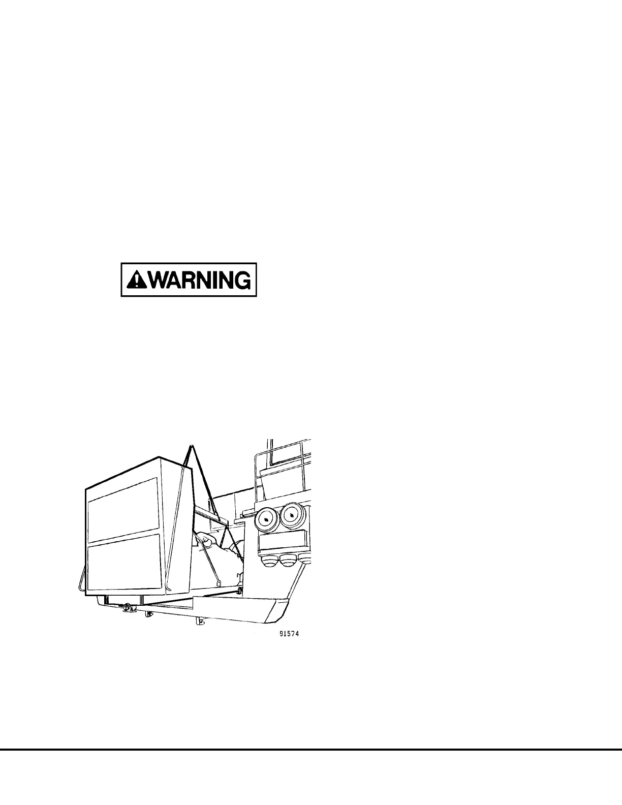
FIGURE 2-8. POWER MODULE INSTALLATION
C02017 03/01 Power Module C2-7
 Loading...


