VALVE BENCH TEST AND ADJUSTMENT
The following parts and test equipment will be required
to completely bench test and adjust the brake valve.
The differential pressure switch can also be calibrated
and operation tested.
• Pressure gauges (3), 0-to-3000 psi (20,680
kPa).
• Hydraulic pressure supply, regulated to 2750
psi (18,960 kPa).
• Hydraulic test stand, Refer to Figure 3-9.
• Hose fittings for valve ports:
Port PX:...................................7/16 in., # 4 SAE
Ports P1, P2, B1 and B2:.......... 3/4 in. , #8 SAE
Port T: .................................1 1/16 in., #12 SAE
• Ohmmeter or continuity tester
NOTE: It is possible to check the pressures with the
brake valve installed and connected to the vehicle.
Remove the brake pedal assembly and actuator cap
and boot assembly to adjust individual brake circuit
pressures.
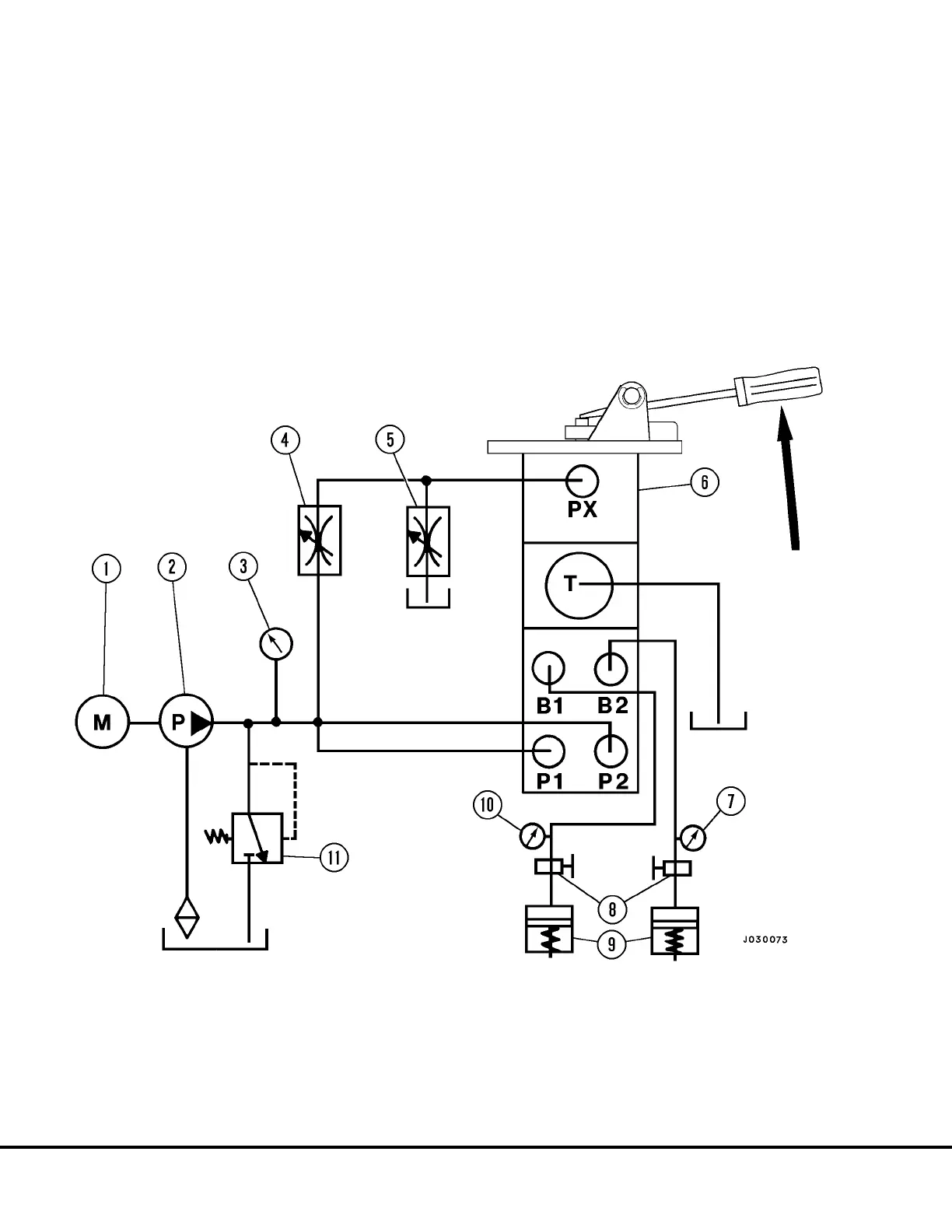
FIGURE 3-9. TEST BENCH SET UP
1. Motor
2. Pump
3. System Pressure Gauge
4. Needle Valve
9. Simulated Brake Volume
10. Rear Brake Pressure Gauge
11. Relief Valve
5. Needle Valve
6. Brake Valve
7. Front Brake Pressure Gauge
8. Shut Off Valves
NOTE: Shut off valves (8) for tests not requiring simulated brake loads, such as circuit tracking.
NOTE: B1, B2 Cylinders must be capable of a 10 cubic inch maximum displacement.
J3-10 Brake Circuit Component Service J03019 1/99
 Loading...


