Steering Circuit Operation
Hydraulic oil from the tank is supplied to a piston type,
pressure compensated steering and brake circuit
pump (16, Figure 2-3), rated at 66 GPM (257 l/min.) @
1900 RPM. An unloader valve (15) maintains system
pressure between 2750 psi (18.9 MPa) and 3025 psi
(20.9 MPa) .
Oil from the pump is directed to a high pressure filter
(10, Figure 2-4) before entering the bleed down mani-
fold (4). The bleed down manifold provides several
functions in the steering, brake, and hoist systems. It
is used to route oil flow to the steering system and
hydraulic brake system. (Refer to Section “J” for brake
system operation.)
Steering system oil is directed to the accumulators (5),
used to store pressurized oil in the event of loss of
pump pressure. Oil is also directed to the flow amplifier
valve (3) for use by the cab mounted steering control
unit and steering cylinders (1).
A relatively small volume of oil is supplied from the flow
amplifier to the steering control unit, mounted on the
steering column in the cab. When the operator moves
the steering wheel, oil is routed from the steering con-
trol unit back to the flow amplifier based on the direc-
tion and rate of speed of rotation of the steering wheel.
The flow amplifier provides a large volume of oil to the
steering cylinders to turn the front wheels determined
by input from the steering control unit.
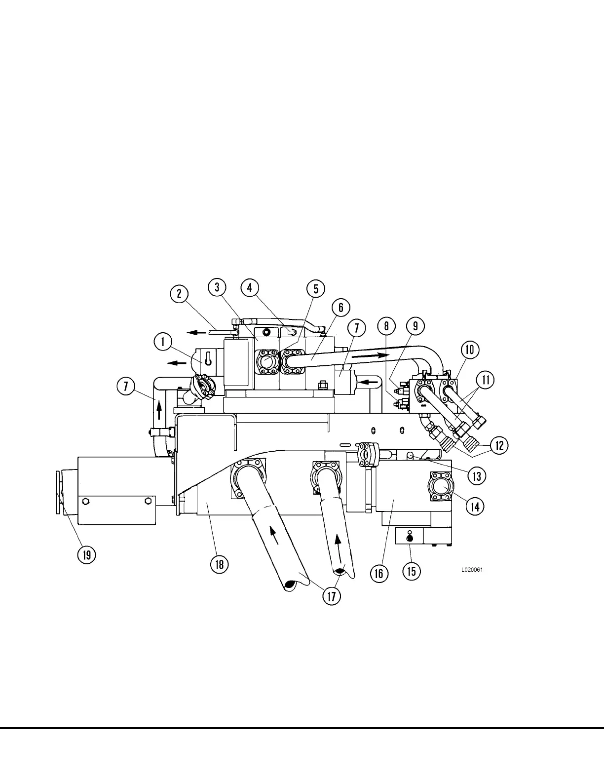
FIGURE 2-3. HYDRAULIC PUMP MODULE
1. Hoist Valve Tank Return (To
Brake/Hoist Return Manifold)
2. Supply to Pilot Valve
3. Hoist Valve
4. From Pilot Valve
5. To Brake/Hoist Return Manifold
6. Work Port Outlet
7. Supply From Hoist Pump & Filter
8. Counterbalance Valve
9. Needle Valve
10. Overcenter Manifold
11. Hoist Cylinder Supply Tubes
12. Hoist Quick Disconnects
13. Pump Case Drain Line
14. Steering Pump Inlet Port
15. Unloader Valve
16. Steering/Brake Pump
17. Hoist Pump Inlet Hoses
18. Hoist Pump
19. Pump Driveshaft
L2-4 Hydraulic System L02028